Nodes are the essential building blocks in the Advanced interface to the Poser Material Room. They are the graphical representation of mathematical function calls, that is: calculation procedures which turn parameters (inputs) to a result (output).
Advanced
The Math group offers various nodes that can adjust and combine colors, images and other texture elements. This article discusses:
- HSV
- Gamma
which modify image characteristics like brightness and saturation. See the overview of the Math group.
HSV
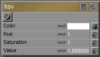 This node takes a Color from its input, usually an image, translates is into HSV mode, adjusts it according to the node settings and delivers the result back as a regular RGB color.
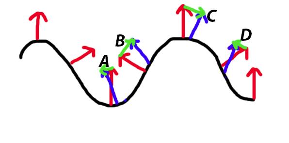
In (its internal) HSV mode, hue determines the color from a 0.0 to 1.0 value. 0.0 represents Red, 0.5 represents Cyan, and at 1.0 we’ve made full circle and are back to Red again. This node takes the hue from the input color, and adds (Hue -1) to its already existing value. So when the Hue value is set to 1.33 it will turn Red (hue= 0.0) into hue= 0.0 + (1.33 – 1) = 0.33 is Green. A value 0.67 will turn Red into 1.0 + (0.67 – 1) = 0.67 is Blue. So an input value 1.0 is neutral, has no effect.
In (its internal) HSV mode, saturation and value determine the mixture of White and Black respectively, with full color pigment. A 0.0 value means no color, a 1.0 value on both means full color. As with Hue, the node values of 1.0 for Saturation and Value have no effect, the difference from 1 is added to (or subtracted from) the original input value.
Gamma
The Gamma node helps me to apply or undo Gamma Correction on specific images and colors, next to an eventual Gamma mechanism applied to all of them (Render Setting). See the fundamental and advanced articles on details, but for short: the images, movie frames and colors handled by Poser are ‘in order’, for input as well as output, and need no adjustment as such.
Poser is using the Gamma ‘thing’ for correcting on its own flaws:
- Direct lights and especially point- and spotlights produce far too deep shadows, while in nature indirect lighting and atmospheric scattering soften shadows a lot. In a similar way, shading effects like Lambert as standard applied in Poser Diffuse are too strong and too dark. This is a generic issue in all CG rendering, not only Poser. Unfortunately, the darkening makes images loose contrast and detail in de darks, which is disliked a lot by most people. That’s a deep down natural thing: the darks hides hunters as well as prey, and we like to be aware.
- Material channels like diffuse and specular are simply added up, multiple lights are simply added up, and all this contributes to overlighting and far too strong highlights (reflections, etc.).
So, as discussed in this article as well, Poser (*) first applies (**) Inverse Gamma Correction to darken (the midtones from) images, frames and color swatches (***), then it renders, and then it applies Gamma Correction to brighten up the result. This leaves the main coloring intact, but softens all effects from shadows, shading and highlighting, and produces a far more pleasant and more natural result which is favored especially in photorealistic render styles.
(*) from Poser 10 and Poser Pro 2010 up, by checking the appropriate Render Setting.
(**) it should not be applied to images which define Bump, Displacement, Transparency or any blending. For those, the neutral / no effect value of 1.0 should be used. For all others, any other value is appropriate, the larger, the stronger the softening effect. The industry standard value of 2.2 is recommended but actually, as images handled by Poser are ‘in order’ and Poser is using the mechanism for its own purposes, any value will do. Values over 1.0 will soften shadows and highlights, values around 2 make a natural impression, and really high values (4.0 and up) might cause artifacts. Render styles which require hard shadows, like comics, do not need the adjustment at all.
(***) Value slot are not affected. As a consequence, a Diffuse (Color, Value) set to (white, 50%) will produce a result different from (50% white, 100%). Also, the output of the Simple Color node will be affected, but the output from the User_Defined node will not, and the image plugged into the HSV node will be adjusted before (!) the HSV adjustment is made itself.
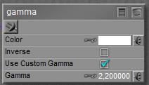 The image plugged into Color can be color-filtered, and Gamma values over 1.0 will brighten the midtones as the node is applying regular Gamma Correction (in math: output=input 1/gamma ). This is to take any Poser adjustments on the input out again before further handling. With Inverse checked, midtones will be darkened as the Inverse Correction is applied (in math: output=input gamma ). This is to put the regular Poser adjustment into colors etc. which are missed by Poser itself, like a User_Defined color. Or to undo the adjustments of a Gamma node applied earlier in the materials node tree.
Use Custom Gamma means: use the Gamma value as explicitly defined in the node. Unchecking this option will use the value as defined in Render Settings. As the latter is recommended for consistency within the scene, checking is meant for introducing Gamma effects in case Poser does not.
Note: although Gamma Correction is available from Poser 10 and Poser Pro 2010 up, the Gamma node itself is around in earlier Poser versions as well. The node can be used to adjust the brightness of image maps used in the scene (like the HSV node), and to build elaborate node trees that address the first portion of the Gamma Correction procedure as supplied in later versions. The node cannot perform the final Inverse correction, as is applied by the renderer to the result.
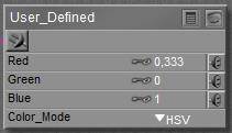 This node produces a color, that is: a three value RGB vector with each component between 0.0 and 1.0, from three independent input values.
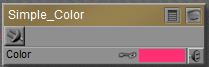 This node produces… a simple color, as set by a color-swatch. Or a simply color-filtering of anything inputted to it.
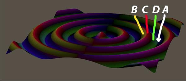
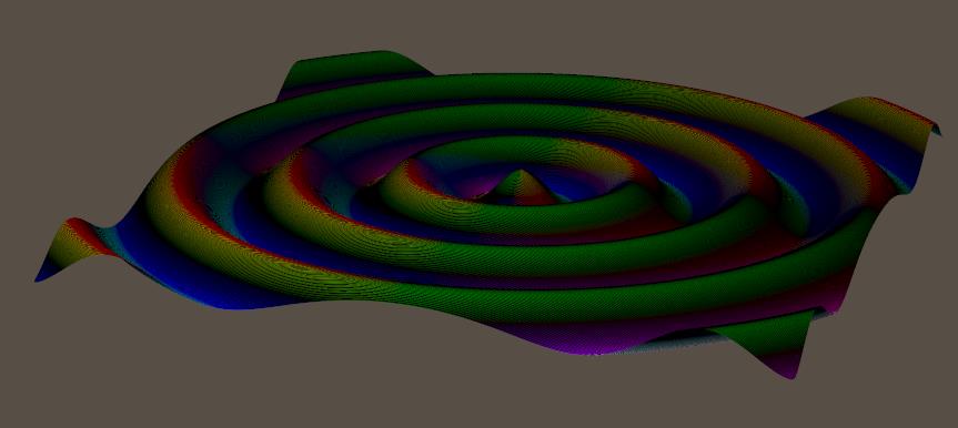
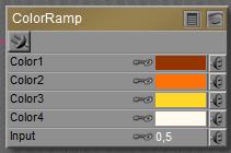 This node produces a color from a four-point gradient, having the color-points set at 0%, 33%, 66% and 100%. The interpolated color is derived from the Input value, which should be between 0.0 and 1.0. I can plug in a greyscale image in here as well, to get it colored up.
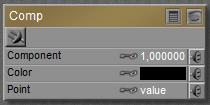 This node accepts a vector, either representing a color (Red, Green, Blue) or a pointer in space (
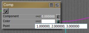 When nothing is plugged into any slot, the appropriate component of the Color swatch is passed through, the Point value is ignored, unless…
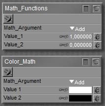 Most functions do what I can expect from them, as defined by any basic math textbook. See the Poser Reference Manual on them in case of doubt. Some operations need both inputs (like Add and Multiply), other operations work on Input_1 only (like sine, square root).
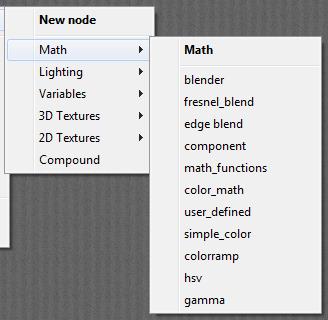 The Math group offers various nodes that can adjust and combine colors, images and other texture elements.
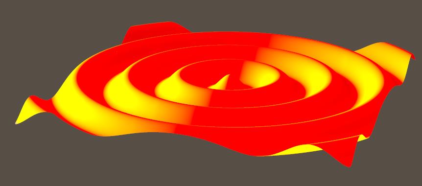
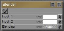 This node takes two inputs, color or image or whatever, and blends them together. When the Blending value equals 0 the result is entirely Input_1, when the value equals 1 the result is entirely Input_2, and the real blends are made by intermediate values.
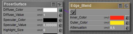 makes
makes 
 and at 0.9:
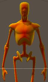
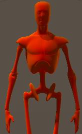
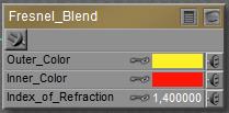 This Fresnel effect in real life concerns the balance between Reflection on one hand (high at the edges) and Refraction (with embedded Transparency, low at the edges) on the other hand. So combining Fresnel_Blend with those respective nodes is an obvious thing to do. For that reason, an explicit
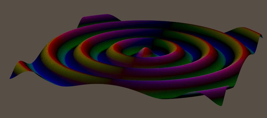
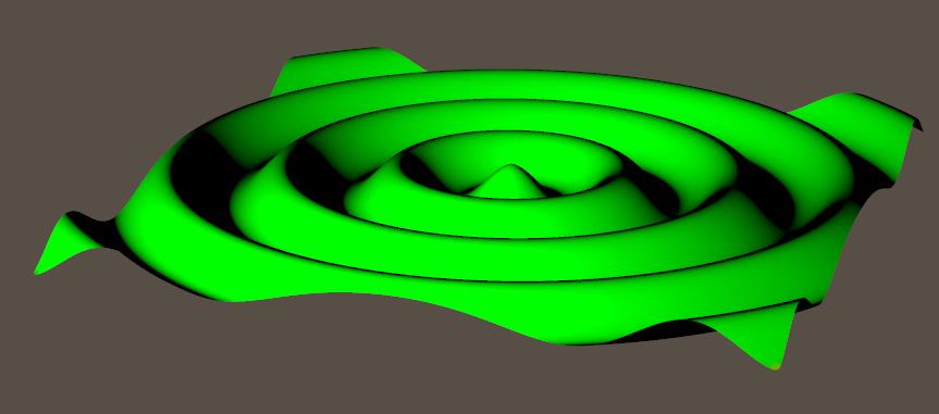
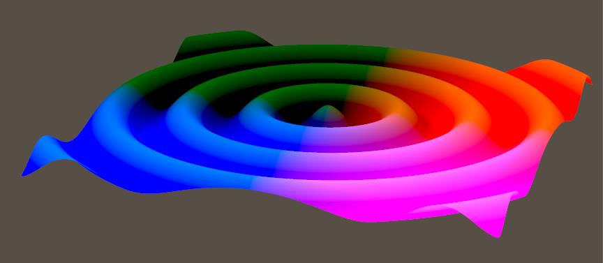
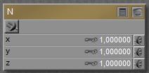 Slightly more intriguing than just single values U and V are normal N and point P:
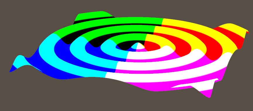
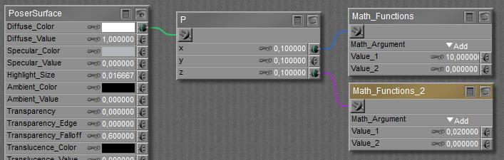
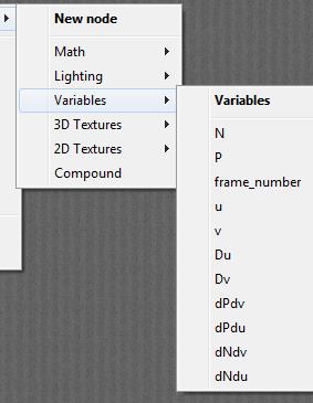
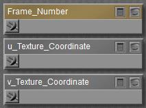 The easiest to comprehend are U, V and Frame_Number. These nodes don’t take any inputs but just report the situation in the scene: at what place on the object surface(U,V, both 0..1) at what time frame the spot is located for which the PoserSurface definition has to report on to the renderer.
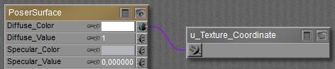
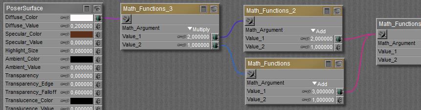
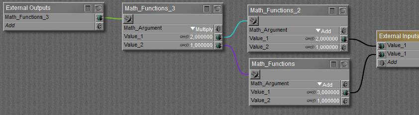
 button), and I can build a complete structure between the final node containing all External Outputs (left in the scheme below) and External Inputs (right in the scheme).
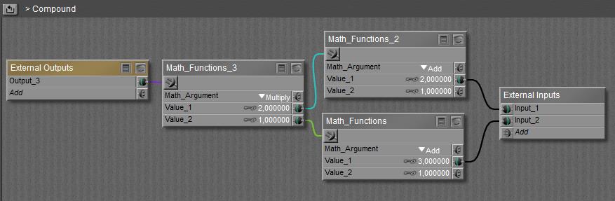
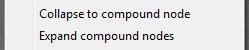
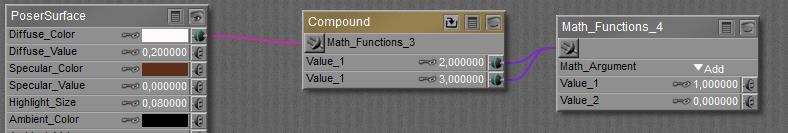
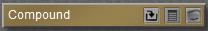
 When done building the node can be collapsed (the
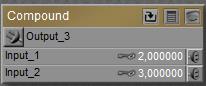
  button) and will just show the outputs and inputs defined in the Material Room definition area: