Dynamics III – 3.2 The list of sims

Each sim is one from the list, and that list includes Cloth sims as well as Hair sims, in the order they are created, whatever their names are. I’ve found no way to alter the order of sims on that list afterwards. As long as each sim is calculated separately this does not really matter, but the menu Animation > Recalculate Dynamics offers the opportunity to re-run all calculations in one go.

Then they are processed according to the list, the ones created first will run first, cloth and hair separate or mixed. As long as sim elements do not collide with each other, there is no issue. But when they do I must create the simulations “from the inside out” to follow the apparent order in their respective effects. For instance: if Vicky is wearing a dress, a coat, long hair and a veil then the sims have to be created (and run) in that order. Dress collides to Vicky, coat collides to dress (and Vicky), hair collides to coat and veil collides to hair and coat.

This implies that a more elaborated scene with multiple dynamic elements really does require some planning, even before starting the creation of the sims. It’s far easier to empty or to eliminate some sims from the list afterwards than inserting an extra sim between to existing ones. And as already stated: I’ve found no way yet to save and load sims from and to the list, or ways to manipulate the list itself otherwise.

Dynamics III – 3.3 Multi-cloth sims

When the scene requires multiple pieces of cloth(ing) to be simulated, the question arises: do I need separate sims or do I put multiple cloth elements in one sim? As in the image, the figure wearing pants (brown), shirt (red), jacket (brown) and cape (green) form the Which Hunter outfit. And we do need Dynamics to make the cape and jacket flapper while hunting, and to keep the shirt under the jacket and over the pants at the same time.

Well, if I put two cloth elements in different, successive sims, I create a sort of hierarchical relationship between two cloth elements. For instance the dress and the coat: if the dress is underneath the coat and the coat does not affect the movement of the dress and the dress might affect the movement of the coat, then the coat can be included in a later sim. Just the dress collides with Vicky and the coat collides with Vicky and the dress, and all is fine.
Unfortunately things work different: the dress does not affect the movement of the coat but the coat does affect (limits) the movement of the dress. Now I can try to collide the coat to Vicky first, and then maneuver the dress in between. I’m not very enthusiastic about that approach, but nevertheless.

Anyway, in some cases using multiple sims instead of just one can help me out. In The Sim List is was already noted that the order in which sims are created is relevant: it introduces some planning beforehand. Something to take into account in that planning as well is that each object can be clothified in one sim only. Once clothified in one sim, it can only be a collision object in others. It’s up to me to pick the right sim at the right place in the stack.

When two cloth elements affect each other, like two dancers wearing wide dresses which collide against each other, they should be in the same sim, and cloth-self-collision must be switched on (third checkbox in the sim settings). When one element affects the other but a hierarchical relationship is not handy (like in the coat-affects-dress example above), they can be in the same sim as well. And when two pieces of clothes do not affect each other at all but share the same set of collision objects, they can be in the same sim too but in two separate sims as well. The first way just reduces the amount of sims and the total calculation time. Even pieces of clothes that do not affect each other and do not share collision objects can be put in one sim, collision objects included. Some collisions will never happen, the sim does spend some time to find that out but not so much.

Example: say I’ve got a leather belt and a piece of cloth, that is supposed to be attached to it. Unfortunately, the 3D meshes are separate. I can make the belt dynamic, and it might quite well get stuck onto Vicky’s hips. But how do I attach the cloth to the belt?

Well, when belt and cloth are in separate sims the cloth can be set to collide against the belt, and the top vertices of the cloth can be put in a constrained group so it sticks with the belt. I create, or at least I run the cloth-sim after the belt sim, and all goes well. This works because the thin linen cloth does not affect the belt-movements while the belt movements do affect the cloth, so the hierarchical relationship holds.
Can I put the cloth and the belt in one sim together? No, because I cannot constrain one cloth element to another cloth element in the same sim. I can only constrain to collision objects, identified for that sim.
But I can put multiple inter-colliding pieces of cloth in one sim, constrain them all to one belt, and put the belt in another (earlier) sim.
Why is there an issue in the first place? Well, the cloth sims take the 3D meshes as they are, and do not care about parent / client relationships which are required for Inverse Kinetics movements, and do not care about conforming settings either. Pieces of cloth are kept together when there are edges between vertices of both pieces, which make them one 3D mesh. When the meshes lack such edges the cloth pieces are considered separate, and the cloth sim might make them fall apart.

Conforming meshes

The Reference Manual is pretty clear:

Objects being converted to cloth must have single-sided, connected (welded) polygons without caps. The exception is decorative objects such as buttons, belt buckles, etc., which should be separate (non-welded) objects. The decorations group favors accessories that are geometrically separated from the cloth mesh object.

Like in real life, buttons should not share vertices with the cloth but it’s handy when there is a little thread connecting the two. But the main point is: lots of clothing meshes are two-sided with caps, as well as non-welded. Various pieces in the same mesh are not stitched together, which make them fall apart during simulation.

As shown above, this is indeed an issue when no hierarchical relationships can be defined, and constraint grouping cannot be used to glue the elements together. In those cases, the 3D meshes should be reconsidered, perhaps pieces can be welded together in Poser, or one needs a separate piece of 3D software to do the job.
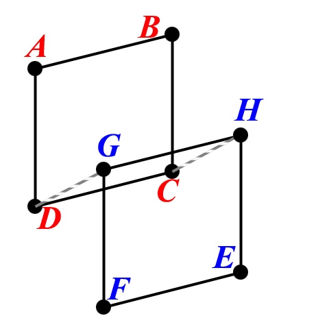
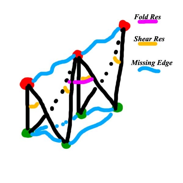
Consider two adjacent quad polys. Ideally, they should have read ABCD and DCEF, sharing the vertices C and D. But in the mesh, we’ve got ABCD and GHEF. In general, there are two variations:

  • G and H share positions with D and C, they are copied vertices. The solution is to un-copy them, that is: welding. Tools can do that.
  • They do not share positions, just the C/H and D/G edges are missing or: the poly DCHG is missing. Those polys have to be added to the mesh, in the proper subgroup. Or the geometry have to be altered by welding C/H and D/G manually. Some work, in any case.

Welding (always make a backup copy beforehand!) however might present new issues. Tools might weld vertices which shouldn’t, especially in double-sided clothing (the sim will fail quite quickly after that). And as welding alters the vertex-count, they might rise issues with the accompanying cr2/pp2 file – which actually should be adjusted to the welding result.

Dual sided clothes for instance present an outside and a lining which are stitched together (with a trim or edge, in the mesh with some kind of capping). This can result in self-poke-through, which especially becomes annoying when outside and lining show different materials. Some possible solutions:

  • Check Self collision and raise the amount of Steps per Frame in the sim settings, so the calculations can solve the issue. This helps to a limited extent.
  • Hide the lining, by assigning it a 100% transparency in Materials Room.
  • Select the lining and make it a Soft decorated group, perhaps the same can be done with the trim. Now all materials can be applied while the outside is the only portion of the mesh in a dynamics group, and dealt with by the sim calculations. Do ensure that the Collision Offset is large enough to fit the lining in between the cloth and the body, and we might need to give the outside a heavier impression since the presence of the lining stuff is not taken into account in the sim any more.

Dynamics III – 3.4 Mesh behavior in short

Actually, Poser performs simulation calculations upon a mechanical structure, which can be represented well by a “spring net”: a structure of small (steel) balls, connected by tension springs and torsion springs. More details on that in Sim Calcs in the Cloth Mesh and Crash Course on… Sims (part V). Those elements interact according to the basic laws of mechanics. Translated to Poser, the balls of the spring net take the interaction with the scene and the collision objects: density, air damping and the frictions. The springs take all cloth-internal interactions: folding, shearing and stretching.

At the start of a calculation, the mesh structures of the clothing elements are transformed into such spring nets. It’s a simple transformation, one-to-one without subdivision (*): each vertex in the mesh becomes a ball, each edge between vertices becomes a tension spring (handling stretching) and between all adjacent existing edges we’ll get torsion springs (handling folding and shearing). This implies that mesh structures with equivalent vertices will differ only in folding, shearing and stretching and not in the other factors. Let’s see how this works out.
(*) when there was subdivision, then the phenomena described in The Sim Engine would not occur. So there isn’t any.

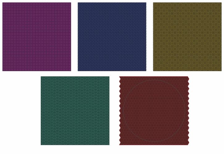
Meshes structures come in sorts, I can’t possibly handle them all. For a particular one, I can ask myself: if this were a real world object build from balls and springs, how would it behave? In this chapter, I consider: Quads, Mono-tris (all diagonals in the same direction), Diamond-tris (or: X-tris, alternating diagonals horizontally and vertically), Fish-tris (or: ZigZag, alternating vertically, same horizontally or vice versa), and Hex’s.

In theory: research reports tell that regularity kills the sim, the more irregular the mesh, the better. Making irregular tri-structures is known as Delaunay triangulation. More on this in Cloth Simulation in Perspective (part IV).

In my observation, the most regular structures have the most artifacts in their behavior. But also:

  • Quads are the best representation of non-weaves like rubber, leather, fleece, etc.
  • Tris are a good representation of normal weaves (linen etc.): mono-tris are the worst, X-tris are the best
  • Hex’s are the best representation of loose knits, like home-made winter sweaters.

Let’s have a further, still undetailed, look into this and apply: horizontal and diagonal pulling, horizontal and diagonal pushing, and shearing, to all of those. Horizontal (or vertical), as in: according to the main edges. But first: what happens when I alter the mesh density?

Mesh density

Doubling the density of the 3D mesh implies: halving the length of the edges, and quadrupling the amount of edges, corners and vertices (doubling in two directions or dimensions, cloth is a surface). What does it matter?

Well, not that much. While I keep the parameters intact, I still get cloth with the same Cloth Density and so on. Stretching, shearing, all remains the same. Even the total amount of folding will not change, as the same Folding Resistance has to be catered for. Except that smaller polys will give me more but finer folds instead of less but larger folds. Bends of the cloth around a corner will be smoother, performed in more, smaller steps. And in the section on thread thickness and Cloth Density (Sim Calcs in the Cloth Mesh) we’ll see that altering the folding relative to the other effects suggests the use of thicker (increase) or thinner (decrease) threads in the weave. In the latter case, the cloth will appear thinner, smoother, silkier.
Note the words “suggests” and “appear”: the cloth behaves as if we’ve changed the parameters, without actually doing so.

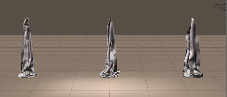
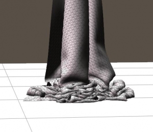
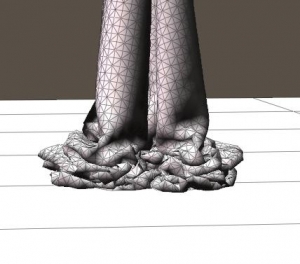
2x2mtr cloth, at densities: 10mm, 20mm, 40mm, 80mm. No difference in shear and stretch. The finer the density, the finer the folds that can be made. The ones at the right are quite heavy.

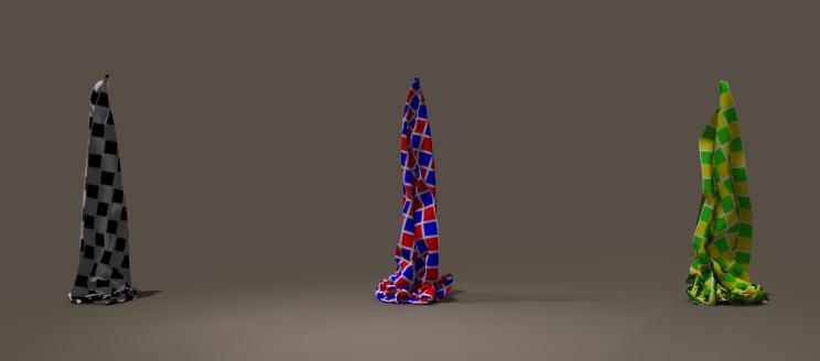
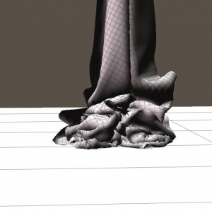
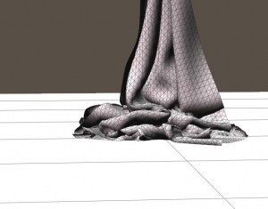
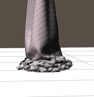
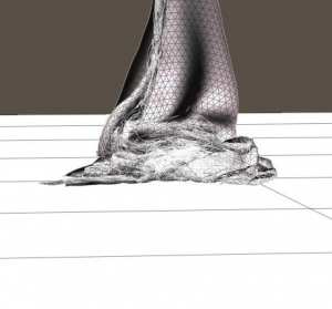
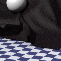
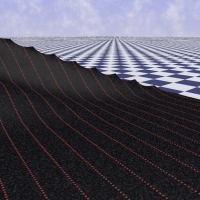
Same cloth 2×2 mtr, quads, hanging at one corner. The left (black-white) one uses 1x1cm polys, shows smoother folds and believable crumbling at the floor. The middle one (red-blue) uses 2x2cm polys, the right one (green-yellow) uses 4x4cm polys. Large folds and artifact’ish crumbling at the floor.

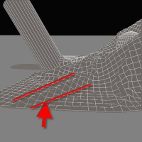
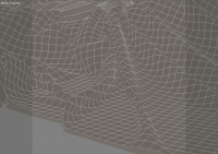
Next image shows the wireframe (anti-aliased).

Note that Android Andy uses meshes of say a 1x1cm density, while Vicky4 comes at about 0.5×0.5 or so. Size does matter. In the fine details, in the final quality. Not in the rough end result.

Mesh structure

No theory, just look at the facts first.

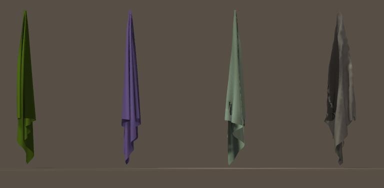
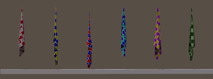
Six different mesh structures, fixed (choreographed) upon the upper row of vertices, all with the same, default cloth parameters, after 30 frames of hanging on their own weight. This is mainly a test on stretching.
Five of them behave more or less the same, the green one at the right is by far more stretchy and elastic, and skews to the right.

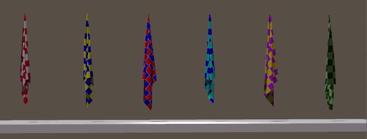
The next figure shows the towels hanging at one corner only (after 120 frames), which makes this a test on shearing, although stretching has effects too. Towels 2 and 3 from the left stretch far more than the others, towel 5 shows larger folds and the stretchy green one does its stretching here as well.

Color Structure Vert stretch Diag stretch Ratio
Red-white Quad

1.3%

4.7%

3.4

Yellow-blue Mono-tri A

0.8%

17.8%

22

Blue-red Mono-tri B

0.8%

22.8%

28

Blue-blue X-tri

1.5%

3.6%

2.4

Yellow-pink Zigzag-tri

1.7%

10.7%

6.3

Green-green Hex

7.2%

12.2%

1.7

Mono-tri A ends the Diagonal Stretch with the diagonal edges downwards, Mono-tri B ends with the edge horizontally.

It’s easy to see that the two Mono-tris (nr 2 and 3 from the left), both with their diagonal edges in the same direction all over the cloth, stretches by far the most in the diagonal direction while they stretched the least of all vertically. This implies that during normal use the animation will tend to jiggle sideways (bottom-right, bottom-left, bottom-right, …) which hampers its use in animations, and will raise the need for longer simulations to get a stable result. It’s quite unnatural for cloth.

The green hex at the right stretches a lot as well, but it did so too in the vertical stretch. The ratio between those stretches, in the table with the lowest value 1.7, means that it stretches about equally in all directions. It’s just very flexible stuff. The Zigzag (yellow-pink, 2nd from the right) makes large folds so this kind of mesh introduces an extra fold resistance.

To some extend these issues can be repaired by altering the parameters. So I set shear (resistance) to 200 and stretch to 100 for both the Mono-tris, and I set fold to 2.5 and shear to 100 for the Zigzag. This equalized the results between the meshes:

Up till now, the quads (red-white) and the X-tris (blue-blue) both make the most normal cloth appearance to me. The hexes (green-green) do make a good cloth too, but a rather flexible kind: good folding, shearing and stretching with the same parameters as the other ones. To me this resembles the behavior of a loose home-knit woolen sweater like my mom made in the old days. The other mesh types can make a decent cloth as well but require higher shear, and either higher stretch (mono-tris) or lower fold (zigzag).

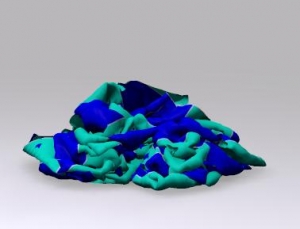
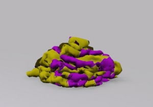
The next test is on fine folding, all the cloth pieces were dropped from hanging on one corner onto the floor. In the animation: each cloth went down during frame 240 to 480, this affected only the corner vertices in the choreographed groups.

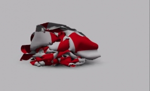
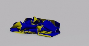
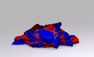
These are quads:

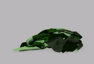
Quads crumble, which gives irregular, sharp edges over the diagonals of the polys. More on this artifact in Mesh-behavior – crumbling.

These are mono-tris:

(diagonal downwards)

(diagonals sideways) – it produces more finer folds than its equivalent. Mono-tri cloth has a directional difference build in.

These are Diamond / X-tris:

This is very believable normal cloth behavior, again.

These are Fishbone / Zigzags:

It looks as if it cannot make sharp bends, the folds remain fattish although the fold resistance was halved already.

These are Hexes:

Extremely flexible stuff, the heap is considerably lower / flatter than the other heaps.

So:

  • Quads do fine for cloth but crumble and ridge when fine folds are formed. Increasing mesh density (vertices per cm2) and increasing the Fold Resistance can help us out. In the meantime the cloth stays somewhat elastic and wobbly. This makes quads best suited for non-woven cloth, like leather, rubber, fleece and the like.
    In addition: use Quads in high resolution (20mm) anyway because too low resolutions (80mm) tend to freeze up. The higher I make the Shear-resistance, the more it looks like leather. The higher I make the Fold-resistance, the more it looks like rubber. In order to turn it from a thicker kind of massive rubber to an elastic band, I have to turn down the stretch parameters.
  • Hexes are extremely flexible in all directions, which normally is not the case for woven and non-woven cloth. Hexes are great for loose knits, like the home made woolen sweaters.
  • That leaves tris for normal, woven cloth. The more irregular the better, the Delaunay triangulation (as applied in Marvelous Designer) definitely is a good idea. From the alternatives, X-tris are the best and show the most natural cloth behavior, especially for silks and satins. Zigzags shear easily and don’t make fine folds that well, which can be adjusted with the cloth parameters (double the Shear Resistance, half the Fold Resistance). Then they make decent linen (burlap, denim, …). Diagonal tris are overly shearing and appear like cheap, wet, elastic towels unless the parameters are adjusted as well (double the Stretch Resistance, quadruple the Shear).
    In addition: At low resolution at medium (50) Shear-resistance it does reasonable cotton or linen, I use Fold-resistance to vary from summer dress (0.5) to thin curtain (500).
    At high Shear-Resistance it might freeze up, at low Shear-Resistance it either makes a wet or an overly elastic impression. At high resolution I can do silk (very low Fold-Resistance), satin (low Fold-Resistance) to chamois-leather (high Fold-Resistance and high Shear-Resistance) but I have to avoid the low Shear-Resistance/high Fold-Resistance combi as the plague. It’s the most unstable thing I’ve ever seen.

Mesh density enables the cloth to make finer folds, like it’s thinner.
From the Marvelous Designer manual: set the Particle Distance to 20-40mm for prototyping and 5-10mm for presentation models. Makes sense. Note that Vicky has a 5mm resolution herself, so you’re always using low resolution cloth on high resolution collision surfaces.

Dynamics III – 3.5 The sim engine

When I run a simulation calculation, a few things happen that are worthwhile to be aware of. Each sim runs in a number of iterative steps, there are two or more of those steps for each frame in the animation. The animation – even if nothing moves or animates – generates the time for the cloth to drape properly, driven by gravity, some wind perhaps, and various frictions and forces within the cloth element, between the cloth elements, and between the cloth elements and the collision objects. The basic idea is that when the cloth is draped well at the start, and the figure gradually moves into a more elaborated pose, the cloth will follow and will drape to that pose accordingly.

The sim settings even offer a Drape-period, intended to have the collision figures change from the T-pose into their frame-1 pose. Or to give the cloth draping a head start, while the collision figures are not moving at all. The advantage of this is that a cloth-sim specific animation is added without disturbing the scene animation as such, the disadvantage is that the movements during the drape period cannot be affected. So arms can cross bodies or legs and ruin he sim instead of helping it forward. When the sim runs during my own animation, I can prevent issues like that by fine-tuning the animation itself before I run the sim calculations.

Hence in general I start with my figures in T-pose at frame 1, give them 1 sec to take a normal pose in normal clothes, or 2 sec for a complex pose far from the T-pose or when in tight, complex or heavy clothing, and maybe even 4 sec in the case of all together. The main issue is: can the pose – in the real world – by a normal, trained – life! – person be made in the period set for it while wearing those kind of clothes?

Okay, the calculations kick in and all parameters describing the physical reality combine with the sim algorithms to make a cloth mesh change shape and position: all its vertices are affected. This is the easy part, and cloth simulators can do it quite efficient. And from the Poser animation, the collision object movements are obtained as well. All this is done per simulation step, defined by: the number of steps per frame and 30 frames per second. So for 4 steps per frame and an animation of 60 frames, the calculation loops 4×60=240 times to cover 60/30=2 sec of animation.
After moving all vertices for that step, the next step is: collision detection.

Collision Offset

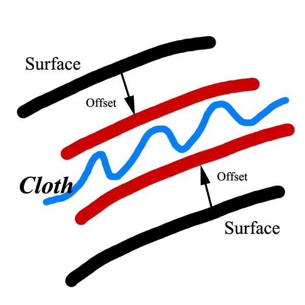
The collision object surface gets a virtual version, by offsetting it towards the cloth surface. Therefore the collision will take place at some distance between the two, which gives the cloth some thickness. There is no extra calculation required, the setting itself does not affect PC resource usage.

  • When the offset value is set (too) high, the result might become visually unattractive and artificial, and the cloth will hardly follow the contours or the body underneath. The Poser upper limit of 10cm hardly makes sense, but even say 2 cm is quite sufficient for emulating a thick overcoat. The default 1cm is meant for thick cloth over a car or statue (note: we’re in Cloth Room, not: Clothes Room). In practice, 0.5 is fine for sweaters and alike and 0.25 will do for lingerie and fine clothing.
  • When the value is set (too) low, the result might show poke-throughs in the render. One reason for that is that the sim does not take render settings into account, and does not take care for polygon smoothing or displacement mapping. And as the cloth and the underlying object will have different mesh densities, they will behave differently in that respect. Another reason is that the body parts perform some strong bends which cannot be supported by the elasticity of the cloth, it just cannot stretch that much. Or the cloth just misses the resolution, it does not have the polygons available in that area to make the bend. All this might be a reason to consider a higher offset value.
  • An issue occurs when a piece of cloth has to maneuver between two surfaces, like Vicky sitting on a chair with some skirt in between. The skirts needs the offset distance to Vicky’s thighs, and the offset distance to the seating of the chair, so when the distance between Vicky and the chair becomes about or less than twice the offset the sim does not know where to more the cloth vertices to. And “not knowing” usually imply: random results, and accidents waiting to happen. This issue might force you into reduced offset values, or might force you to alter the scene for instance by moving the chair a bit down and back, or by shrinking it a bit in one direction (say Y) while growing it in another (say: Z). But then you’ve got effects in the visual results.
  • A second issue comes with the concept. When a piece of cloth surround a body(part), then each cm offset will increase the circumference with about 6cm which will generate stretch forces within the cloth, except when the cloth itself has been widened beforehand. But that’s about 5% extra for a dress or sweater, 10% extra for the legs of pants, and 15-20% extra for sleeves.
    This is one of the issues when clothifying conforming clothes: they either do not support the extra widening, nor does Poser support the relaxed stretching in one direction while not stretching that easy in the other direction (otherwise, sleeves that widen easily will lengthen easily as well, which is not what we want). At least, not in a simple way.

Collision Depth

To find out for which vertices collision calculations have to be performed, a layer with the thickness defined by Collision Depth is imagined around one of the surfaces (cloth or collision object, does not matter, all movements and positions are relative anyway), and the vertices of the other surface are tested against it.

  • Simplified: about all vertices within that layer are taken for further investigation, and all other ones are not. Of course the actual method is a bit more elaborated, but this is the idea. The larger the Depth value the more vertices are investigated upon, and the calculation times will go up accordingly.
  • When the Depth is (too) high, the layer becomes too thick and the mechanism runs an increased risk on “false negatives”, vertices that should not be considered for further treatment but nevertheless gets some, with sometimes erroneous results. Hence a limitless expansion of the Depth does not resolve all issues. Though, despite the Poser maximum of 10cm for this parameter, I rarely use values over 4cm myself.
    Perhaps an even better rule is: start with the Offset value, and double this once or twice but not more.
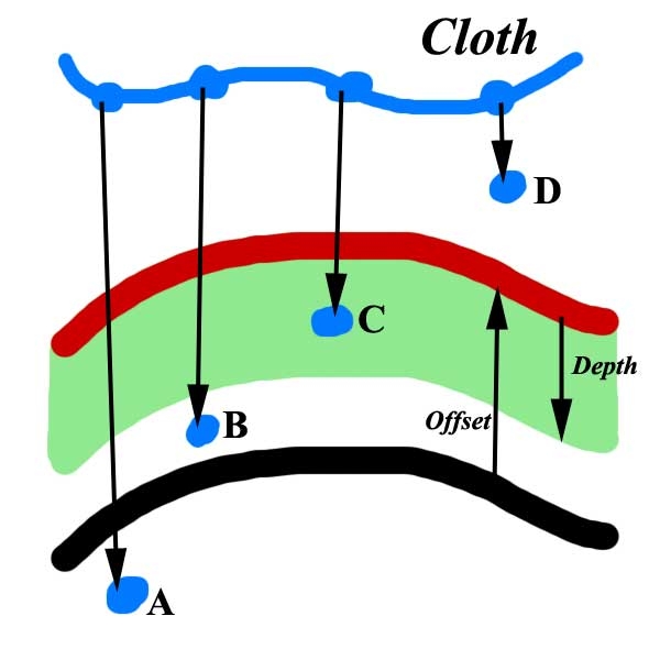
  • When the Depth is (too) low, a vertex that approaches the other surface with a high velocity has a change to pass through unnoticed.
    See the figure: vertices A and B might pass through unnoticed, C is captured and D does not collide.
    For instance, in 1 second, with 30 frames a second, and 2 sim steps per frame, each step covers 1/60 of a second. So when Vicky and a skirt around her thighs come down towards a chair over a distance of 60 cm within that 1 second, then within the 1/60 of that sim step the vertices move 1 cm towards the colliding surface.
    Not that much you think, but when the Depth is just 0.5cm the vertex might be at one side of the capturing layer in say some step N, at the other side of that layer in the next step, and won’t be marked for investigation at all. From that moment on, the cloth has entered the inside of the body and it’s just a matter of time for the simulation to crash.
    This is where increasing the Steps per frame value becomes of help: it further limits the distance the vertex can travel, and increases the change of being captured by the Depth-trap considerably. For the example above: doubling the Steps from 2 to 4 reduces the time between steps to 1/120th of a second, reduces the distance travelled by that particular vertex to 0.5cm, and so when the vertex in outside the detection layer in step N, it just will be in in the next step but won’t pass through unnoticed. And the sim-crashing stops right there.
    Doubling the Steps Per Frame roughly doubles the calculation time for the whole sim. This makes it quite an unpopular – but quite effective – method.
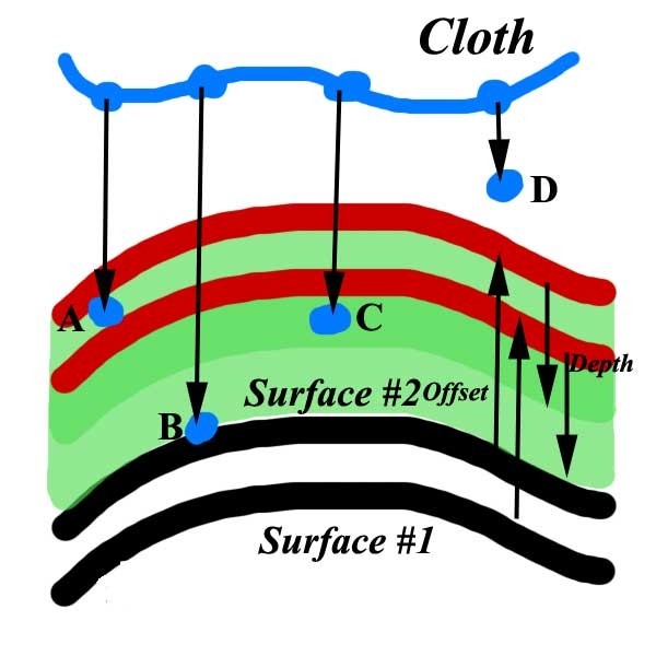
  • An issue occurs when the cloth approaches two surfaces (at the same side) which are quite close together. For a thin object, this means that the collision warning method sees both sides of the object and gets really confused when the detection layer is too thick. As it seems to collide against both surfaces, the final result gets a random component and the vertex might end up at the wrong (back) side of the object.
    See the figure: vertex A is captured in the surface#2 handling, B will end up at the wrong side as being captured by the surface#1 handling, and C might go either way.
    Therefor I avoid depth values which are larger than (half) the distance between two of those nearby surfaces. This puts a maximum value to the practical use of Depth. The downside however is that I have to start ramping up the Steps per frame value earlier.
    Don’t underestimate this. The front and back side of finger surfaces are about 1 cm apart (a hand on chest makes the shirt go wild), chair seatings might be less than 1 cm thick (and the dress falls through), and if a coat collides with a shirt and a body, both are less than 0.5cm apart. Reduce the collision depth and increase the steps per frame, and take the increased calculation times for granted. Repairing crashing simulations take longer.

Notes on the Reference Manual

  • The Collision Offset parameter determines the distance between a cloth object and a collision object at which the collision detection calculations begin. Increasing this value can help avoid accidental collisions, especially during animations, because Poser requires a little time to calculate actual collisions. Increasing this value too high can consume extra computing resources.
  • The Collision Depth parameter specifies how close the cloth object must be to a collision object in order for a collision to take place. Increasing this value increases the distance at which the cloth and collision object will collide. This is useful when creating clothing, because the cloth will be kept away from the figure. Increasing this distance makes the cloth appear more static but avoids having body parts penetrate the cloth (such as a leg poking through a skirt).

The correct definitions are exactly the other way around. Offset determines the thickness between cloth and object, help reduce poke-through and can make the cloth look static, while Depth defines the collision handling process and can require more resources.

  • The Collision depth and Collision offset dials are limited to minimum 0.1cm and maximum 10cm.

Collision Depth has a minimum of 0.0 mm

  • Before adjusting these settings, be sure to enable the Object vertex against cloth polygon and Object polygon against cloth polygon options in the Simulator Settings dialog. You may also try reducing the Steps per frame value from its default of 0.2 to as little as 0.005.

It’s proper policy to check those options before increasing Steps per Frame. This parameters is limited to whole numbers from 2 to 33333.

  • The Collision Depth and Collision Offset dials emulate thickness by “extruding” the cloth inwards by the amount of Collision depth units and outward by the amount of Collision offset units. Thus, the cloth now has a “thickness” of collision offset + collision depth. Any specified collision object intersecting this volume will be treated as a collision.

Actually, offset and depth are parameters for the collision object (in a specific sim). The object is extruded towards the cloth with an amount Offset, and then this virtual surface gets an inward thickness Depth. All cloth vertices in and around this area are seen as collision candidates and prone to further evaluation.

Collision tests

Once the vertices are labeled for further testing, those further collision tests come in flavors:

  • The default one is called “cloth vertex against object polygon” and it works fine for cloth with high mesh densities against objects with a low(er) mesh density. This usually is the case when we throw a large cloth over a car or a statue, or a table cloth over a table.
  • The next one is called “object vertex against cloth polygon” and does the opposite, so that one works fine for high density body’s colliding with low(er) density clothes. For clothing, this is a normal situation. Most clothes I see passing by show vertices 2 to 5 cm apart, while Vicky’s body itself shows vertices only 0.5cm apart. In practice, this extra option hardly adds to the calculation times but hardly adds to the solution as well.
  • The serious one is called “object polygon against cloth polygon”, is more calculation intensive but far more effective as well. It also captures vertices that were about to escape by passing through the Depth layer, and therefore, with a bit of the previous option as well, is some alternative for increasing Depth and/or increasing Steps per frame.
    This is why I mentioned those options first in my “recipe” chapter (Quick Clues and Recipes, part II), and this is why the Poser Reference Manual states that when you consider increasing the Steps you’d should check these options first. They might just do the trick and are far less computational intensive.

The calculation pass

As said: each loop starts with a physics/ real world related pass through the vertices. Such a pass can be made in two ways:

  • The new position, velocity etc. for the vertices in pass N are derived from the previous pass N-1, but the new information within pass N is not used until the next pass N+1.
    This makes all vertices considered equal so let’s call this the “symmetric approach”, but there will be two full intermediate results (N-1 and N, N and N+1, …) which have to be stored and the simulation will converge gradually to its final state as a lot of the intermediate information is not used.
  • The new position etc. for a vertex in pass N is also derived from the new positions, velocities etc. of the already handled vertices in the same pass. Now only one intermediate result has to be stored and all available information is used so the sim converges faster to its final state. Of course, this is the way Poser does the job.
    But this way it matters in which order the sim calculates through the mesh, as vertices are not equal: one is first, others are later, hence: the “asymmetric approach”.
    Say, one vertex is pulled down, by gravity. Then the vertex next to it will also be pulled down, but will also be pulled in the direction of the first mentioned vertex. So forces start skewing a bit, and not all mesh structures are equally happy with those diagonal forces.
  • Who cares? Well, for cloth pieces falling on cars, or a lot of clothing following an animation sequence, the result will not be exactly as in real life but still quite believable. The “asymmetric approach” is quite handy for practical use, though scientific sims always want the best match to real life and take the symmetric route.
    But the effects become noticeable in simple straightforward cases, like draping a banner down.

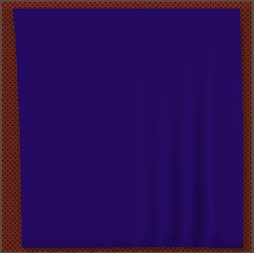
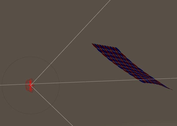
For instance, the image shows what happens with a simple square cloth made of little quad polys just hanging down under its own weight. It skews to the bottom right, with some extra tension at the left side and more folds in the right half.

I’ll tell you: the sim loop starts at the bottom right, and then goes to the left and up. That is: against the UV coordinates, from high to low. Left or right is a choice, but bottom up makes sense as the usual driving force behind cloth sims is gravity, pulling down.

Something you can do about? Well, it mainly happens with rather low (10 or less) settings for Shear and Stretch Resistance. You can raise them, or dampen the effect by raising the Stretch Damping, or take it for granted when it does not hurt the final result too much. But at least; it’s the sim itself, it’s not you.

Sim details

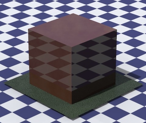
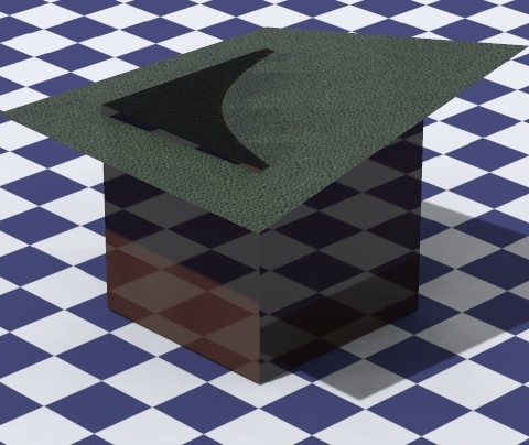
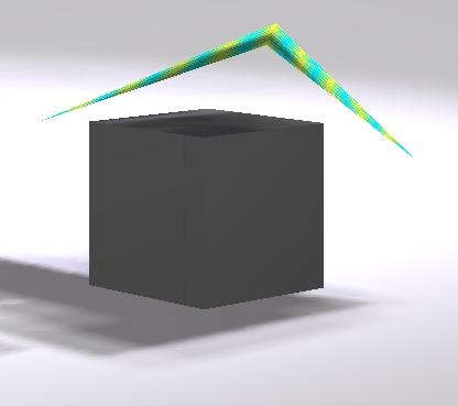
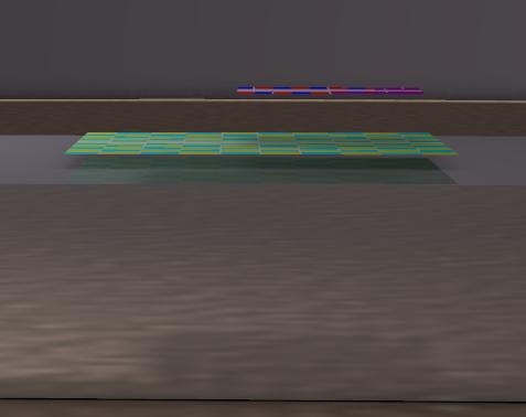
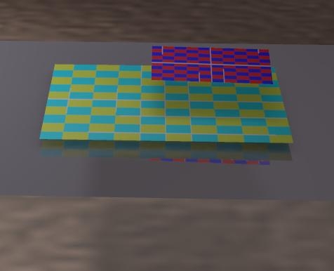
This is a simple cube (images by Bagginsbill), and a simple four-vertex square piece of cloth. With no additional options checked, the cloth falls right through the cube. This can be expected, as “cloth vertex against object polygon” is the default setting, and no cloth vertex touches the cube surface while falling down.

This shows that the sim mechanism does not perform any additional subdivision within the cloth, it just works with the mesh information.

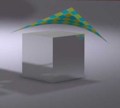
With “object vertex against cloth polygon” checked the cloth is stopped by the cube, with an artifact. Three corners seem to fall through a bit, and the fourth one does not. Why is that?

Well, each time first the position of a vertex is calculated from the forces, velocities and other physical aspects. Apparently, in this case, the vertex ended up just below the surface level of the cube. Then the collision detection kicks in. For the first cloth vertex down and three up, no cube corner passes the cloth polygon. Nor does this happen when the second and third cloth vertex come down. But when the forth cloth vertex comes down, all four cube corners pass the cloth poly. Collision detected! And that forth vertex is put back at the offset height above the surface.

Why is the image showing things a bit different then?
That is because the renderer is smoothing and slightly curving the surface, while the sim calculations do not. When I connect the lower left corner of the cloth and the upper right one b a straight line, the upper left cube corner will be underneath. The Poser preview hardly smoothes either. As a result, the renderer might show poke-through while the preview does not, or the other way around, while the sim thinks it’s doing fine given the options checked and the time and step sizes that the calculations was allowed to use.

Why aren’t the lower vertices falling down anymore? What makes this a stable solution?
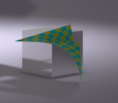
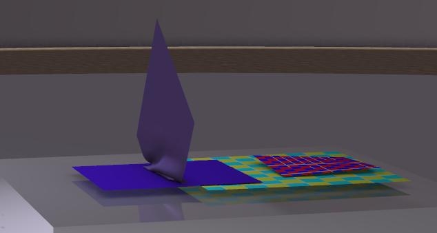
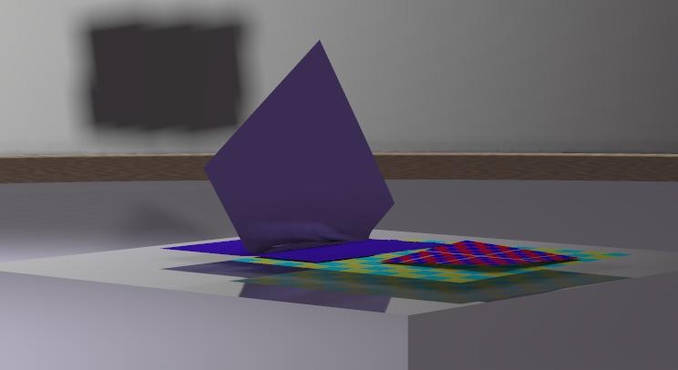
So I tried again, different offset (5cm). The preview shows that this is about the minimum distance of the cloth above the surface, but above the surface only. Over the edges of the surface, the vertices are looking down at the ground. The sharp fold is smoothed out in the render. End 100 frames later, the solution is not that stable after all, and the cloth sails to the ground.


By just expanding the box I made the cloth fall right onto the surface. All issues were gone, and all four cloth vertices ended somewhat above the cube surface, at a distance dictated by the Collision Offset for the cube.

Now I was a bit curious to the cloth self-collision mechanism. Two simple four-vertex cloth pieces ended up on top of each other. One at the offset distance above the cube. The second a 7cm distance above the first, a distance that did not change whatever parameter I adjusted.

However, such a thing did not happen when I used two pieces of cloth with a high resolution of vertices (100×100 quads instead of one), it did not happen when a third piece of cloth was added to the sim, and also more elaborate setups did not show this hovering behavior any more.

In other words:
watch out for the overly simple pieces of cloth. A piece of 10,000 polys behaves different that a piece of one poly.

Dynamics III – 3.6 Sim calculations on the Cloth Mesh

After working a while in the Cloth Room, people feel that mesh structure and mesh density make a difference. The 3D mesh of the cloth element in the sim does affect the result, the dynamic behavior of the cloth and the calculations themselves. Some believe that the mesh in a way is translated to a mathematical simulation structure. Such a structure, in mechanical simulations, can be thought of as a “ball-and-spring network”. The balls take mass and some friction and damping, the springs take stretching and folding forces and the like, and some damping as well.

I’ll give the mere details of such sim structures in Crash Course on Physics… (part V), and present some summary in this chapter.

In the meantime people question: will the mesh be triangulated first, will it be subdivided first, or refined during the process when necessary? The answer, to my understanding, is: NO. The 3D mesh IS the structure. The vertices of the mesh become the balls, the edges become tension springs that resist elongation (so you’ve got to apply a pulling force), and between two adjacent or opposite edges we can find torsion springs that resist rotation (so you’ve got to apply torque). That’s about it. Period. Cloth has no equivalent for compression springs which resist shortening. I cannot shorten a cotton thread by pushing against its ends, can I?

So a coarse mesh with large polys, long edges, a few vertices will become a sim structure will long springs and large, heavy balls. And a fine mesh becomes a structure with many small balls and short springs. And tension springs are stiff, they cannot bend themselves, they can stretch only and shrink after being stretched first. Un-stretching is a better term better I think, they cannot really shrink but behave like fixed size rods when relaxed.

The connections between balls and springs are very flexible, but the springs around a ball are interconnected by torsion springs which limit the ball-and-spring poly in its deformations. I’ll discuss a load of examples further on, but the bottom-line for now is: if the edges lack in the 3D mesh, then the tension springs will lack in the sim structure, and the interconnecting torsion springs will be absent also. As a result, various mesh structures will behave different to various deforming forces.

Translated to Poser Cloth Room parameters, the balls take care of:

  • The dress’ weight, aka: mass, aka: Cloth Density and so the interaction with gravity
  • Air damping, aka the interaction with wind and atmosphere
  • Friction (Collision, Dynamic, Static and Self-), the interaction between cloth elements and the collision objects when not colliding but sliding along each other.

These parameters themselves will affect the behavior of the cloth, but for given parameters the mesh density and structure have no further impact. I’ll discuss these parameters in chapter Cloth parameters – sim side and Cloth parameters-real world. They make the cloth move, and might generate the forces for deformation, but do not determine the deformation of the cloth by themselves. These parameters, represented by the balls in the simulated mechanical network, represent the interaction of the cloth with its environment.

The springs cater for:

  • Fold, Shear and Stretch resistance
  • Stretch damping

These do determine the deformation of the cloth. The effect not only depends on the values of the behavioral parameters but also depends on the mesh density and structure. Given values will result in different effects for different meshes.

In addition:

  • Density and Air Damping are allocated evenly over the balls. Frictions are applied to those balls that make contact with the collision objects.
  • Shear and Fold Resistance are allocated evenly over the appropriate edge-pairs in the spring net. Quads, Hexes and X-tris have equal corners per vertex (quad:4, hex: 6, X: half has 4, half has 8 corners per vertex). Diagonal and Zigzag have 6 unequal corners per vertex: 2x 90° and 4×45°.
  • Stretch Resistance is allocated evenly over the edges, proportional to the edge length. So all springs stretch with the same percentage when the same force is applied. Mind that diagonal springs are longer than straight ones.

Forces in short

Stretching – means enlonging the tension spring by pulling. When it’s stretched, reducing the pulling force shortens the spring until it’s relaxed again and it won’t shorten any further. When I pull, the spring pulls back. As long as I pull harder than the spring, it keeps on elongating. When it’s got longer, it pulls harder until we pull equally hard (in opposite directions) and reach equilibrium. From natures laws, the forces applied are then proportional with (that is: a constant times) the relative elongation of the tension spring. Relative, so it does take a specific force to elongate the cloth x%. If the same force is applied to a longer spring it will stretch more in cm but an equal percentage. The constant involved is the Stretch-Resistance.

When I hang a weight onto a tension spring and let it go, it will jump a bit up and down (springs always come with vibrations), but this mechanism will lose its energy and the weight will come to a rest. This speed of energy loss is Stretch Damping, which stops the vibrations in due time.
In a mesh, stretching causes two adjacent polys to stick in the same plane.

Folding – happens when the stretching springs cannot shorten any more, hence: the cloth is relaxed. Now the tension springs start behaving like incompressible rods, and any pushing will force two adjacent polys to go out-of-plane. The cloth is folding. But the two opposite edges are connected by torsion springs, which resists any change of angle, with a force proportional to the angle of deformation. The constant involved is the Fold Resistance of the cloth.

In life, there are limits to folding and stretching cloth, as it may tear, the threads in the weave may snap, there is mainly resistance against folding at high speed but not when doing things slowly, and the folding springs might cause vibrations which require damping as well. Poser does not support all that.
But Poser does support the concept that Folding and Stretching are opposite phenomena. I cannot stretch and fold the cloth in the same direction (or better: opposite directions) at the same time. As hanging curtains show, I can stretch vertically (weight, gravity) and fold horizontally. For folding vertically, the gravity has to be countered first.

So I put my hands on a piece of cloth on the table, and move my hands in opposite directions, away from each other. That’s stretching. Moving them towards each other: that’s un-stretching first, then it becomes folding.

Shearing – happens when I fixate the cloth with one hand, and move it up or down with the other hand. A quad-poly will deform in a straightforward way: the angles between adjacent edges change though but all edges themselves keep their length. Note that this is the opposite of Stretching and Folding, where – for a quad poly – the angles between adjacent edges do not change but the edges change length (stretching) or not even that (folding). The counterforce by the cloth comes from torsion springs between the adjacent edges, they apply a force proportional to the angle of deformation. The constant involved is the Shear Resistance of the cloth.

In life, shear resistance in weaves is the result of the friction between adjacent threats in the cloth, depending on material, thread thickness and weave tightness. When this friction is high, you will have extra trouble bending and stretching the cloth as well, but it does not work the other way around: tablecloth does hardly stretch but shears well. And when cloth stretches easily one might expect easy shears too. This certainly holds for knits, but non-woven cloth like leather and rubber might be different. Shear for non-woven is something for the micro-fibers and molecules that make up the stuff.

Thicker threads
Let’s do some additional real life stuff: what happens when similar cloth gets made from threads which are twice as thick (diameter). For the thread itself, Weight per unit of length, Stretch Resistance and Shear Resistance will quadruple (2nd power) while Fold Resistance will octuple (3rd power (*)). But I will only need half of the amount of thread to make the same size of cloth, so finally cloth density, stretch- and shear resistance will double while fold-resistance will go fourfold: thicker stuff behaves much stiffer.

(*) folding a thread actually implies stretching the core and then make the bend. With a double-thick thread, the stretching itself goes against a four-fold cross-section and hence a fourfold stretching force, and against a doubled amount of stretching to make the same folding bend. That makes eight-fold. Also the bend itself faces a fourfold cross-section and a doubled amount of stretching. Doubling thickness makes eight-fold counterforces.

So, density, shear and stretch resistance behave the same when comparing A) one piece with double thick tread and B) two thin pieces of cloth put together. Relevant, as the latter occurs when I fold a piece of cloth at the edge and stitch things together to make a neat edge to a T-shirt or table-cloth or alike. Folding behaves different: two non-attached (!) thin layers have half the folding resistance of one thick layer. So my T-shirt edges might do something in between, when doubling cloth thickness I can go threefold here. How about the other parameters?

  • Air damping: thickening the thread will double the distance air has to travel around it, but we only need half the threads so cloth out of thicker threads will experience the same Air Damping. A double-layers piece of cloth on the contrary will experience double the Air Damping as the air has to flow through both pieces.
  • Stretch damping: any thread in a weave is made of many thin threads working in parallel. Doubling the thickness of a thread means a fourfold of thin threads in there, so I need four times the force to stretch the thread, and it loses energy four times as fast as each thin thread just continues its behavior. So as I need half the threads to make the same cloth, like stretch resistance, stretch damping will double when the cloth thickness doubles, whether it’s caused by thicker thread or by multiple cloth layers.
  • Friction: in Poser, the parameter values are determined by the materials the cloth and collision objects are made off, and size, thickness, density and the like are not included. So thicker threads or multiple layers do not affect these settings. In real life, weaving cloth with a thicker thread might give a rougher surface (more friction) with less contact to the object (less friction). Hence, no direct need for adjustments but do make some when you feel for it.

Weave tightness
Next to thread-thickness, weave-tightness is a cloth characteristic too. What happens when a loose weave is compared to a tight one, with say twice as many threads cramped in?

Again, the Frictions won’t change a bit. Density, stretch resistance, stretch damping, and fold resistance too will simply double for twice as many threads of the same thickness. Air damping sees twice the amount of threads too and will double. That is; double at least because a tight weave might block the air streams through the cloth far more. Will it go tenfold? More? Shear resistance will double at least too, twice the threads will experience twice the friction between them when shearing. But when the threads are really crushed together the threads will deform a bit, the contact surface between the threads increases, and the force that pushes those surfaces onto each other increases as well. Will it go tenfold? More?

Scaling
Let’s test the last way that can spoil our fun: if I take a cloth 1×1 m in size with 1×1 cm polys, and I scale it to 200%, and I compare it to another cloth 2×2 m in size with 2×2 cm polys (so: the meshes look exactly the same), will I get similar results?
Yes, I will. That saves the day, what I see is what I get.

Conclusion
When I want to consider thicker cloth (say: double), I can leave all Frictions as they are and raise all other parameters with the same relative amount (double also). This represents adding a second layer to the cloth.
When I want to represent single-layer cloth with a doubled thread, I raise the folding (till maximum fourfold) and reduce the Air Damping (till one-fold = no change) and alter the friction somewhat to my liking to represent a rougher cloth surface structure.
When I want to represent a single layer cloth with a doubled weave tightness, I raise the Air Damping and the Shear Resistance till whatever makes me feel comfortable.
When I want to represent a single layer cloth with a mixture of thicker threads and increased weave tightness, I just mix the two mentioned adjustments accordingly. For instance, I leave the Air Damping just at the doubled value (both methods sort of cancel out), and raise Folding and Shear Resistance.

Note that for non-weaves (rubber, fleece, leather, …) the concept of weave-tightness is rather meaningless. For those kinds of cloth materials, I just stick to the “thicker thread” idea when considering thicker cloth.

The other way around
Imagine, someone says: “these … are the parameters describing cloth material X”. Then do I need to know the thickness? First: no I don’t. Because we’ve seen that I can represent a thicker or thinner material by adjusting the density (that’s in grams per cm2) and all other parameters increase or decrease proportionally – except for the Frictions which don’t change at all.
Second: yes I do, so I can take it into account for additional fine tuning of the Folding, Shear Resistance and Air Damping adjustments as described above but also take it into account for adjusting the Collision Offset which emulates the cloth thickness in the final result.

Poser parameters

Up till now I discussed the phenomena Stretch, Shear and Fold as they are considered in math and physics theory. Great, we’ve got the idea now, haven’t we? But… is Poser really working that way?

No it is not. Like in real life, stretching, shearing and folding all come together in the result, I can’t have isolated effects (except for laboratory situations). So does Poser, and actually: it improves the believability of the sim outcomes.

Let’s refer to a previous example of the banner hanging down. At low parameter values it becomes visible that the result not only shows stretching but also some skewing (hence: shearing) and some folding too. And when I start playing with the parameter values, I find that altering the shearing resistance does effect the stretching of the cloth too, and altering the stretch resistance changes the shearing of the cloth.

In other words, the physical, real world behavior is determined by a mixture of the parameter settings. And the other way around, it will be hard to determine the proper parameter values by measuring real world values. Is all lost then?

No, some generic rules could be observed:

  • The total amount of stretching and shearing does not depend on the values for Fold Resistance or Stretch Damping. So, it’s only Stretch and Shear which hang together.
  • When the Stretch and/or Shear resistance is increased, the stretching will get reduced, in all cases and combinations.
  • While the Shear Resistance is smaller than the Stretch Resistance, the result is only determined by the Stretch Resistance. When the Shear Resistance gets increased above the Stretch Resistance the total stretching reduces further. Up till now I’ve not obtained any further understanding of the underlying mechanisms or principles.
  • The default is 50 – whatever it means, and noticeable differences in result require “order of magnitude” steps. Halving, doubling, tenfolding, like that. From 50 to 75 makes a difference, from 50 to 55 does not.
  • Within the range of normal values, that is: 5 .. 500 (tenfold up or down), each doubling of the Stretch Resistance about halves the amount of stretching (as long as it exceeds the Sheer Resistance). So when a value of 50 stretches the cloth 50mm, then a value of 100 will stretch the cloth about 25mm as expected from physics theory.

Dynamics III – 3.7 Mesh behavior – crumbling

One major issue that came up when discussing Cloth Room in the Renderosity forum was crumbling, very well documented by Bagginsbill.


Let’s consider a quad mesh, with the edges in horizontal and vertical (or: UV-) direction. Stretching, folding and shearing in those directions happen in a straightforward way. So let’s look when forces are applied diagonally.

When pushing, the cloth might fold diagonally without having direct counterforces available: no edges, hence no springs. Shear and fold work against it a little bit, but generally are not strong enough to push all the surrounding cloth away. So it’s easy to bring the opposite vertices together. This is exactly what causes the “crystal ridges” as artifacts in the cloth. And for quads those ridges can exist in both diagonal directions, so crumbling is caused when some of those ridges come together and combine effects.

This is different in tris, which have a diagonal edge in at least one direction. So mono-tris still might ridge in one direction but are hard to crumble, X-tris, Zigzags and Hexes can resist ridge forming in all directions and won’t crumble.

What might help against ridges in quad meshes?

  • Not using quads resolves this to some extent, and smaller quads make smaller ridges
  • Increasing shear and/or fold resistance will push the crumbles out. But high shear and fold resistance will affect other behavior of the cloth as well, life is a compromise. Reducing mass (density), friction and other effects will make this pushing more successful. So instead of raising fold/shear resistance, reducing density is an option. And as shear and fold resistance work together in this case, you can do with less fold and more shear.

Engineering stuff

For those who like the formulas for a better understanding.

Consider a quad, three vertices in a plane, the fourth one out of plane. If the distance to its opposite vertex (in the same poly) is 100% in case the vertex IS in plane, then now it’s shorter: X% instead. When X=0 the quad has folded completely into a double sided triangle.

In this out-of-plane position, this quad and its neighbors make a shearing force S*(90-a) with S the shearing resistance (equal or related to the Poser parameter, one never knows) and a the angle between two adjacent edges (orange, in the scheme). At a=90° (perpendicular), shearing is null while each deviation generates deformation of the quad and counterforces accordingly.
The quad and neighbors also make a folding force F*(180-b), with folding resistance F and b the angle between opposite edges (pink in the scheme). At 180° the edges are in line, no folding, and any deviation generates folds and counterforces accordingly.

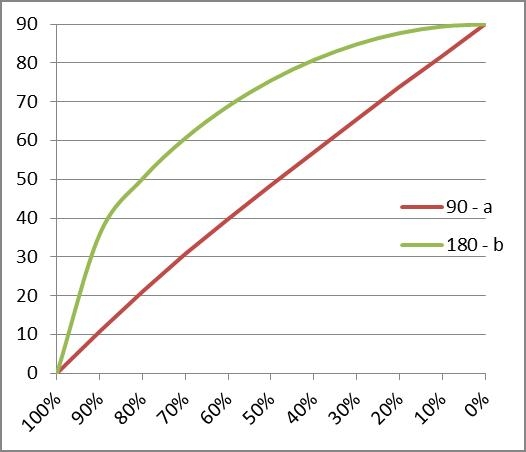
From geometry, we’ll have Sin(a/2) = ½ * sqrt(2) * X and Sin(b/2) = ½ * sqrt(2) * sqrt( 1+X2 )

For each X there is a valid combination a and b (see the graph), so for each X there is a ridge-resisting force. The ridge only disappears when this force is larger than the counterforces for friction and gravity.

At the left, say X=90%, we find (180-b)=40 and (90-a)=10, a 4:1 ratio between (anti)folding and (anti)shear. Halfway, at 50% we’ll find a 1.5:1 ratio. So when reducing the (anti)folding with 1, the (anti)shearing force should go up with at least 4 to 1.5 to get a similar result. Otherwise things get worse.

Dynamics III – 4.0 Cloth Parameters & the Real World

Via the sim mechanisms and via the cloth parameters, the real world is sneaking into our comfortable and manageable virtual Poser environment. This implies that understanding the real world enhances our abilities to handle Cloth Room, and vice versa, handling Cloth Room requires the understanding of the real world. Which brings the high school books on geometry and mechanics on our desk.

I like that, I got my MSc in that arena (a very long time ago). You might not, no apologies needed. Just pick up the clues, the results, and skip the intermediate steps. I’ll mark them as clear as possible. You might like it, to some extent, but you may consider to skip the advanced parts. No apologies needed for that too. I’ll mark the advanced steps as clear as possible as well. When there are a lot of them, I’ll put them in separate chapters but sometimes I don’t. Simply because it’s a bit annoying to scatter a single subject all over the tutorial.

A word of warning on all the details. In the previous chapter Cloth parameters – the Sim Side I’ve discussed that

  • It’s not the values themselves but the ratios between them that make the difference, especially when considering Density, the Dampings and the Resistances.
  • When the values hamper a decent progress of the calculations or hamper the creating of a good result, then change them (while keeping the ratios if possible). Some cloth may look like leather and drape like leather and behave like leather, but that’s only relevant when the sim comes to an end in due time and shows a decent result by itself.
  • So, the real world values are mainly of help to obtain reasonable parameter sets for cloth materials. Nothing less, nothing more.

And on top of that, the cloth sim itself resembles some workings from nature, following the laws of physics. Understanding of that can help to understand the sim, and hence might be valuable to make the changes where we need them to get the desired results. And to make them more efficiently and effectively, without endless trials and errors.

In the meantime, in might be profitable to understand more about cloth in general. Just cotton will do, I guess. Two Wikipedia articles might open, or close, your eyes:

while another article might give a nice overview or insight in textile properties:

  • http://na1.northsails.com/North_Cloth/fiber_properties.html as seen by a high-performance sail maker

Dynamics III – 4.1 Density, Air Damping and Wind

Most Poser Rooms are on the details of scene building, and Pose Room itself is all about virtuality. Size does hardly matter, when everything is doubled in size you still might get the same result. Things are relative (with a few exceptions, like some parameters in the new scatter node and some camera settings).

Cloth Room is different. Although the Stretch, Fold and Shear parameters define the behavior of cloth related to itself, and the Friction parameters define the relationship between cloth and the objects in the scene, the Cloth Density and Air Damping introduce real concepts like gravity and an surrounding atmosphere filled with air. They cannot be turned off, and are the essential driving forcing of everything that further happens in the Cloth Room. No sim without gravity. So let’s start there.

Density and gravity

In Cloth Room, take a piece of cloth, pump up the density (increase mass) as well as the Fold etc. resistances (stiffen it), zero the Air Damping to eliminate the air-effects, drop it from some height and look up your high school mechanics formulas, and the Earth gravitational constant. They apply. Use 30 animation frames for 1 second, and you can predict when the thing hits the floor.

H = 1/2 * g * f2 or f = sqrt(2*H/g) with height H in cm, gravity constant g equals 1,089 cm/f2 and f the time in frames.

In detail: Earth gravity reads 9.800 m/s2 on the Earth surface. There are differences, it’s 9.832 at the poles and 9.780 at the equator as the Earth is not a perfect ball, and it varies a bit with underground and surroundings too. But 9.800 is a decent average. That value, converted to 100cm/m, equals 980 cm/s2 and another conversion to 30fps makes 1.089 cm/f2.

Density in Poser is grams per cm2, 1 g/cm2 equals 10kg/m2 which equals 10.000 kg (10 tons) per m3 for a sheet 1mm thick. Office paper is “80 grams”, per m2 that is. A0 flip over / poster size is 1 m2. I’m a 6 feet guy , I guess my summer pants take about 1 m2 = 10.000 cm2 of cloth, when I put them on a kitchen scale it reads say 250 grams. So the Poser setting would be 0.250. Just measure up your own clothes, and you know. These are my findings:

Density, gr/cm2 Weight (grams) Surface (cmxcm)
0.005 Poser default
0.007 Post-its, based on block of 100 40 7,6 x 7,6
0.008 Normal office paper 80 gr/m2
0.012 Very open lace-like cotton shawl 20 80×20 avg
0.012 Small pattern lace top 40 40×80
0.020 Thin summer dress 200 90×110
0.020 Inkjet photo paper (200 gr/m2)
0.021

0.018

Flag

Banner to the flag

300

60

90×155

18×155

0.026 Kitchen towel (for drying dishes) 100 62×62
0.028 Thin shirt 200 70×100
0.029 Open weave / lace-like vest 140 60×80
0.041 T – shirt (short sleeves, good – bit thicker – stuff) 260 70×90
0.045 Thin pants (0.5mm) 500 115×100
0.046 Thick shirt (0.5mm) 320 70×100
0.046 Sweater – industrial knit 500 90×120
0.047 Small kitchen towel (for wiping hands) 100 44×48
0.052 Large bathroom towel 700 90×150
0.055 Sweater – home knit 600 90×120
0.071 Fleece (thick stuff, you know) 600 70×120
0.075 Jeans 600 80×100
0.078 Serious sweater, really warm 840 90×120
0.095 Tie (double/triple layered, lined etc.) 40 110×6 avg
0.256 Leather belt (in pants, just less than 2mm) 100 3×130
0.418 Leather belt (over 3mm, tough to fold) 460 10×110
0.70 – 0.90 Metals sheets 1mm thick (so 10.000 kg/m3=>1g/cm2)
1.91 Gold sheet 1mm (note: Poser has 1 for upper limit)
0.27 Aluminum sheet 1mm
0.5 Wood, 7mm (in case you want a wooden tie)

Thin shirt, Wooden tie.

Air Damping and Wind

Air resistance is similar. Ignoring units for the moment it’s the force generated by an air flow of 1 m/s through (or at) a 1 m2 cloth surface. I can measure it. I take a cylinder (Poser primitive), make it long enough, put it horizontal as a flag pole, and attach a piece of cloth. I just collide it to the pole, and put one row of vertices in the constraints group. Now I’ve got a flag. Or I lose the pole and put the upper row of vertices in the choreographed group. Same to me.

I drape it, after some frames it will hang down properly. Now I can apply wind force, from the menu, let’s make it from aside. The wind will blow it aside, gravity will pull it down and the angle that results from the simulation tells me the relationship. I vary air resistance and density and the angle will exactly vary as expected. We’ll do that later.

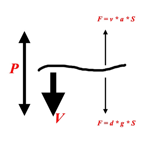
First I redo the dropping experiment. I take the cloth up but now I give it meaningful density and air resistance values. Like the default ones, which are suggested for table cloth. I drop it (now the cloth moves, instead of the air, doesn’t matter), and note that it takes a bit longer to hit the floor. If I drop it from larger heights, and note the intermediate results, I can observe that it reaches a constant velocity going down. The cloth moves through the air, the resistance generates a force upward. Gravity pulls it down, and increases the velocity. Therefore, the air resistance force will increase, until it equals gravity. Then the forces are in equilibrium, and the thing will not accelerate any more.

Just another way of deriving the air resistance value, as the final steady speed v (cm/s) reads: v = g *d / a

For speed in cm/s, gravity g (980 cm/s2), density d (gram/cm2) this implies air damping a to be in gr/cm2 per second.
And for the Poser default values d = 0.005 and a = 0.02, I get v = 980 * 0.005/0.020 = 245 cm/s

So now I understand air resistance, in its simplest form, and I can check out the Wind Generator using the flag as described above. I give the cloth maximum stiffness (fold etc), zero friction, and default density and air resistance.

Then I put a Wind Force generator aside, and make it blow straight into the cloth. I give it some distance (twice the cloth size will do), leave the generator angle at 45°, and give it a serious range (4 to 5 times the cloth size will do). A Wind generator is quite a rude thing actually. It will produce the full force in an area determined by angle and range, and nothing outside it. No fall offs like spotlights. I leave the Amplitude at 1, the question is what that means.

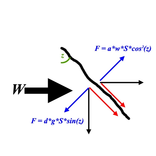
So I run the sim, and find the flag hanging at an angle of 45°.

Now I know what’s meant by Amplitude = 1. That’s the wind that – when blowing horizontally – will push a default piece of cloth up with the same force that is exercised by gravity to pull it down.

More precise, a wind speed w will hang the flags at angle z, where w = g * d/a * sin(z)/( 1-sin2(z) ).
So when the flag hangs 45* for the default values d= 0.005 and a=0.02, then Windforce amplitude 1 implies w = 348 cm/s.

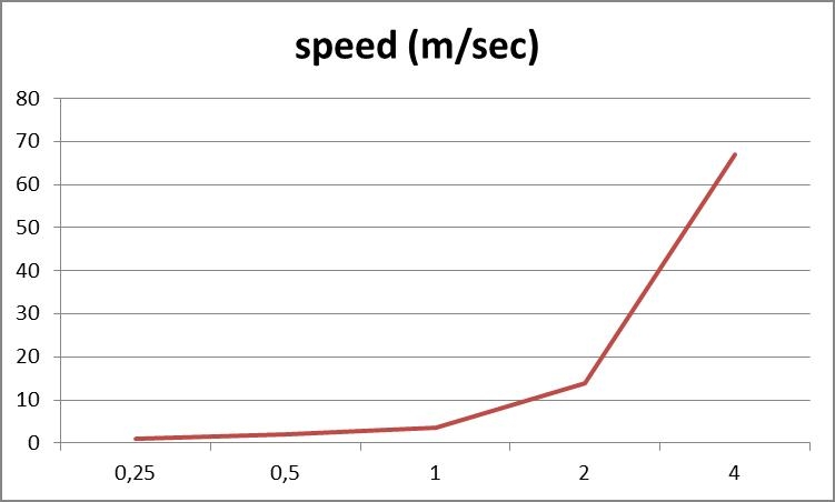
What will happen to the wind speed when I adjust Amplitude? For this, I had to repeat the sim at various amplitude settings.

  • Amplitude 2 created an angle of 66,5, that’s a windspeed of 1360 to 1400 cm/s, that’s about 4 times as fast.
  • Amplitude 4 created an angle of 80-78, that’s a windspeed of 8000 – 5500, or: another 4 times as fast again.
  • Amplitude 0.5 gave an angle of 34, that’s 199.3 (say 200) cm/s, or roughly half as much compared to amplitude 1.
  • And Amplitude 0.25 gave an angle of 22, windspeed 106.7 (say 100) cm/s, or another half as much again.

It looks like the amplitude and windspeed relate in a linear way below amplitude 1 or a 45* flag angle (half the amplitude gives half the windspeed), and relate in a squaring way (double the amplitude quadruples the windspeed) above amplitude 1 or a 45 flag angle. This gives artists more control in both regions, as if the dial changes sensitivity.

Wrap up

Gravity acceleration in Poser is 980 cm/s2. It is slightly different from the one used in the Gravity script from the Scripts menu, so take care when mixing results from both. I’ve not looked at the Poser Physics application yet.

Density in Poser is gram/cm2, so the default 0,0050 means 50 grams/m2, about half the value for office paper and good for light silk. The max 1.0 means 10 kg/m2 which is about a sheet of lead of 1 mm thick, or a piece of usual cloth material, 1 cm think.

Air damping in Poser is gram/cm2 per second. An object that feels a force will accelerate, the air damping will increase with velocity, and this results in a maximum speed for the cloth relative to the wind/atmosphere. So when my figure is wearing a gown, and some body parts are moving at about or above this speed limit, we can expect the cloth sim to break or to show that the other forces have to work hard to make it possible.

For a force of 1G (normal gravity pull) this speed is v = g*d/a for the Poser dial values d (density) and a (air damping). So our default light silk reads: v = 0,005 * 980 / 0,02 = 245 cm/s (=> 2,45*100/30) = 8,16 cm/frame. So, at this speed the cloth feels a windforce with is equal to the gravity force pulling it down.
245 cm/s is pretty fast, but sometimes our animation moves about the same speed or faster and then the cloth is facing windforces of 1G or more. For instance, if my 180cm large figure in the scene makes a cartwheel then the feet will travel a distance of 2*pi*180/2 = 565cm in say 0.7 sec gives 800cm/s and hence a long skirt requires a 3.3G force at ankles height to move forward. Such a force requires high values for Stretch and Shear resistance and a large number of steps per frame in the calculations to prevent is from ripped apart in the sim. The good news is that the cloth will be pushed against the legs with that same force, so we’ll need only a little bit of friction to keep it in place.

Windforce amplitude in Poser represents windspeed in cm/s, that is : amplitude 1 applied horizontally to a cloth of default material (light silk) pulled down vertically by gravity, will bring the cloth into a 45 degrees angle. That results in : 346 cm/s. For amplitudes below 1 the dial behaves in a linear way, so 0.5 implies half the windspeed. For amplitudes above 1, doubling the dial value quadruples the windspeed. This translates into :

  • amplitude 0,10 is the upper limit of Beaufort 0, calm, smoke plumes going up straight
  • amplitude 0,50 is the upper limit of Beaufort 1, light air, smoke plumes tell the wind direction
  • amplitude 1,00 is the upper limit of Beaufort 2, light breeze, feel the wind, leaves whisper, minor seawaves
  • amplitude 1,25 is the upper limit of Beaufort 3, waving flags, whirling dust, moving leaves
  • amplitude 1,50 is the upper limit of Beaufort 4, waving hair, whirling paper and fierce moving leaves
  • amplitude 1,75 is the upper limit of Beaufort 5, moving branches
  • amplitude 2,00 is the upper limit of Beaufort 6, strong breeze, problems with your umbrella, large seawaves
  • amplitude 2,25 is the upper limit of Beaufort 7, hard wind, really hard to walk of cycle against the wind
  • amplitude 2,45 is the upper limit of Beaufort 8, stormy, falling twiggs
  • amplitude 2,65 is the upper limit of Beaufort 9, storm, falling branches and (roof)tiles
  • amplitude 3,00 is the lower limit of Beaufort 12, hurricane

All this is relevant for those who want to combine poses, moves, cloth sims and falling props into one believable shot. The max value 4 seems nice for extreme comic scenes, the wind will turn you inside out.

For instance: at amplitude 2, the wind speed is 3,46 * 22 = 13,84 m/s. At default cloth density and air damping, this will exercise a force of 13,84 / 2,45 = 5,65 G’s on the cloth (see above, a force of 1G relates to a windspeed of 2,45m/s). Gravity G times 5,65 requires a figure working very hard to walk slowly forward against the wind, and also requires large stretch resistance values to prevent the gown from being shred in pieces.

So I do hope that some understanding not only enables you to make believable dynamic clothes, but also to make believable dynamic pictures.

Reality check

Let’s reconsider some Poser default values.

The default cloth density reads 0.005 which represents light silk. From the measurements however it appears that the tenfold, 0.050, is a better representation for normal cloth. A quarter of that (0.012) for lace, half of that (0.025) for thin clothing (thin shirt, summer dress), one-and-a-half of that (0.075) for thick cloth (jeans).

Now, I hang my flag down. In my observation, a Beaufort 3 is required to skew my flag (density 0.02, see table) at at most 30*, that’s about 540 cm/s wind speed while sin(z)=0.5.

Using the mentioned formula w = g * d/a * sin(z)/( 1-sin2(z) ) I get a = 980 * 0,02 / 540 * 0,5 / (1-0,25) = 0,024 instead of the default 0,02. So regarding to the flag the default Poser cloth density is fourfold too low, and the default Poser air damping is just a bit too low as well.

Note, as you can see in all formulas, it’s the ratio d/a that comes back each time. This means that when I change them in sync I’ll get the same physical results. For the default setting, this ratio is 0.005/0.02 = 0.25. For my flag it’s 0.02/0.024 = 0.83. I can also rephrase this as: regarding to the flag, the Poser default stuff offers far more air damping for is density. Which is quite an adequate description of the tight woven light silk, which gently floats down when I drop it above the floor.
Hence, I either set my density to 0.02 and the air damping to 0.024 or I leave the density at its default 0.005 and reduce the air damping to 0.006. For flags that is. Change things when you do know different. Just for making waves on a little bit of wind, flags have a higher air damping than standard linen. Light silk also is different, silk is known for its specific high air damping due to its very tight weave: it hardly lets the air pass through.

So as far as I can see now, Poser default represents light silk. Not table cloth, not flags, not heavy cloth covering cars and statues, not shirts, not jackets, not jeans, not medieval gowns. Light silk.

As far as you consider the use of wind force for some extra dynamics in the scene (like photographers are using a wind machine as well during photo shoots): meaningful amplitudes are between 0.5 and 1.5, and the default 1.0 is a very reasonable default.

Living in another world

Poser Cloth Room is supposed to represent Earth surface, as I can find a decent fit for its gravity and atmospheric density, from cloth drop and flag tests (see next section). This makes me curious: can I mimic other environments as well? It would be handy to have dials for gravity and atmosphere, but there aren’t.

On the Moon, gravity is low (16.7% of Earth), and so it’s on Mars (37.7%). On Jupiter, it’s large (236%). Venus and Saturn have about Earth values. Under water, there is an additional upward force (lowering gravity for the moment) which is proportional to the difference in density between the object and its surrounding water. But since cloth is organic, there is not that much of a difference, except for clothes that are filled with air initially. Fleeces, woolen knits and thick weaves for instance. When the air is gradually replaced by water, they sink like the rest. So for well dressed mermaids, I don’t have to correct for gravity.

To mimic low gravity, I can either increase all parameters except density (for the moon: 1/16.7% = 6-fold), or do the reverse. That is: reduce density (for the moon: 16.7% of the initial value), increase the frictions anyway (!) and leave the other parameters alone. To mimic high gravity, I can either reduce all parameters except density (for Jupiter: to 1/236% = 42%), or do the reverse: increase density (to 236% of the initial value), reduce the frictions anyway and leave the other parameters.

On the Moon and on Mars, the low gravity results in a low atmospheric density as well. Jupiter is different, it’s a gas planet without a surface, it just gets denser the way in. Its “ground level” is defined as the level where the atmospheric pressure equals 1 (Earth) atmosphere, and its composition is very light (mainly hydrogen and helium). But we might want to do high densities anyway. Like under water, where moving cloth definitely is something different. The basic idea is: I just have to reduce (thin atmosphere) or increase (thick atmosphere) the Air Damping, and I’m done.

The Moon effectively has no atmosphere at all, so air damping can be zeroed out. The Mars atmosphere has a low pressure (0.01 Earth atmosphere), but is quite thick thanks to the carbon dioxide and so it supports serious winds and dust storms. I tend to reduce Air Damping to 10%, like I would for Jupiter for its thin atmosphere. Venus on the other hand is extremely hostile, with an thick carbon dioxide and sulfuric acid atmosphere, temperatures from 400 to 700K and an atmospheric pressure of about 90 Earth atmospheres. Not for tourists. Air damping needs to be tenfolded or – like under water – hundredfolded for realistic results, which will bring me at the limits that the sim will support. But I can also reduce the density, and the other parameters (except the frictions) instead. Because it’s the ratio that counts in the sim result.

The issue with large (relative to density) Air Damping, is that it limits the speed which one can move. We know all that, from our attempt to run in a shallow pool, or from attempts to swim with our daily clothes on. The Cloth Room is not different. In real life, the cloth will hamper our movements and we’ll need serious forces to get the job done. If the cloth cannot stand the forces, the fibers will snap and the cloth will tear. In Poser, figures can apply unlimited forces onto the cloth, and its fibers won’t snap. But I’ll need a hell of a Stretch Resistance to keep the cloth in decent shape under those forces, and so things tend to grow out of hand. Many Steps per Frame, and so on. A better way is to slow down the movements, or even reconsider them. Again, if it’s hard to do in real life, then it’s hard to get it done properly in Cloth Room as well.

Engineering stuff

In this section I’ll present some further details on gravity, and handling air damping. For those who did well in physics class, and want to verify (and approve upon) my findings.

On gravity, I’ve noted that the Gravity Script (in Menu > Scripts > Utility) not only let the object bounce (with 50%) on the floor, and on the floor only (Y=0) without any possibility to alter things, but also contains the code lines:

  • g = – 0.005        \ this is the Earth gravity acceleration in the script
  • loop :
    • v = v + g    \ velocity starts at 0, and increases downwards on a per frame basis
    • y = y + v        \ height starts at Y in scene, and decreases on a per frame basis

in that order.

Some things are wrong here:

  • in the script, gravity is expressed in Poser Native Units (1PNU=262cm) per frame squared. From the metrics g=9,80m/s2 this means 0.00416 for 30fps or 0.00598 for 25fps. The value used in the scripts is about the average of those, so the result is about equally inaccurate in both popular playback speeds. It also deviates from the Cloth Room value which exactly matches the Earth value of 9,8 m/s2 on 30fps.
  • The second phrase is correct, it determined the velocity at the end of each frame. But the third phrase misses the point that it should use the average velocity during the frame period, and not the end value. So actually it should read: y = y + (v-g/2). As a result the object displaces too much per frame, it moves too fast according to its speed, and according to the laws of physics. This comes on top of the error in the gravity value itself. For 25fps these errors might cancel out a bit, but for 30fps the errors add up.

So it’s a fun, but inaccurate script which might reveal its surprises the moment you use it next to your cloth sims in the same scene.

On air damping, air is flowing through a piece of cloth, at some velocity v. There is an air pressure difference P between both sides of the cloth. The ratio between those is the air resistance, a. Then P = v * a.
For those into electronics: it’s similar to Ohm’s law, Voltage V, current I, resistance R: V = i * R. Only this time, air is flowing instead of current.

The air pressure (difference) creates a force perpendicular to the cloth, proportional to the amount of cloth (surface S):

F = P * S (add in P=v*a) = v*a*S

Now, consider our drop-drown experiment. There is no atmospheric movement but the cloth is flat falling down at speed v, same effect, same force. But initially, the cloth is dragged down by gravity, at a force F=d*S*g . Same surface S, mass density d (kg/m2) and Earth gravity acceleration g.
While the gravity pulls the cloth down, it accelerates, speed increases, upward air damping force increases and finally, both forces equal out. From then on, the cloth falls down unaccelerated, at constant speed.

From the equations we can see that from that moment a*S*v = d*S*g. The surface cancels out as the result is the same for any size of cloth (and any shape, as long as it falls flat). And the final speed reads v = g * d / a.

When v is in m/s and g in m/s2, then the ratio d/a is in sec. All other units in d and a should be similar, so if d is in g/cm2 as the Poser manual tells us, then a is in g/cm2 too – per second. For v in cm/frame and a per frame as well, gravity should be in cm/f2 (value 1,089).

We know the basic formulas for non-damped motion:

  • acceleration g, which is a constant
  • speed v = g * t, increasing at constant rate over time t
  • displacement h = 1/2 * g * t2

Now for air-damped motion:

  • acceleration g – v * a/d, gravity minus air damping, it varies with speed v itself. So
  • speed v = d*g/a * [ 1 – e ( -a/d * t) ] and therefore
  • displacement h = d*g/a * { t – d/a * [ 1- e ( -a/d*t) ] }

Now back to Poser. I took my cloth, raised it to 19,6 mtr, set folding etc to the max to make it stiff as a marble plate, but kept density and air resistance at default values. That’s 0.005 gram /cm2 for density and 0.02 gram/cm2 per second for air resistance. The ratio a/d reads 0.020/0.005 = 4 /sec, and that implies that at 1 sec, the exp(…) part in the formula is reduced to less than 2% and can be ignored, to simplify calculations.
That means: 19,6 mtr = 0,25 * 9,8 * ( t – 0,25) or : impact at 8,25 sec, that’s just beyond frame 247 (poser time in cloth room is always 30fps, whatever your animation settings). That’s theory.

Sim run. Drop down. At frame 247 it’s just above the ground, at frame 248 it has had the full hit. That’s Poser reality meets theory. Great.

On Wind force, let’s do the math first too. Take angle z as the angle between the flag and the vertical. Z = 0° means hanging down, no winds, and z=90° means a horizontal flag, extreme winds.

The (vertical) gravity force on the skewed flag can be decomposed in a part along with the flag, stretching it and being countered by the pole (if we had one), and a part perpendicular to the cloth, making it rotate downwards. This latter force is F = d*S*g*sin(z), d for mass density, S for cloth surface, g for gravity acceleration constant.

The (horizontal) wind force has a similar effect, but we have to adjust for the fact that a skewed flag will present a smaller surface to the wind. Again, the force can be decomposed into one along the flag stretching it as well (you know cloth is pulling when the wind blows in), and a force perpendicular, rotating it upwards:

F = a*S*w*cos2 (z) with airdamping a, windspeed w (in m/s), surface S and the cosine squared thanks to the mentioned adjustment.

The flag hangs at equilibrium when both rotational forces cancel out, and since cos2 equals 1-sin2, we can make it to

0 = a*w*sin2 (z) + d*g*sin(z) – a*w

From this we learn that when airdamping a or windspeed w equal zero (no atmosphere, or no wind) then the equation reduces to sin(z) = 0, z = 0°, flag hangs down. And we learn that when a and/or w grows really big (under water, hurricane) then the equation reduces to sin(z) = 1, z=90°, flag fully stretched horizontally.

From this we can determine the meaning of Amplitude 1: we just solve the equation for z=45° and find a windspeed of 3,46 m/s. Default density at 0.005, default airdamping at 0.02.
Now I know windspeed, air-damping, mass density and the gravity constant values, I can easily predict the angle or calculate windspeed by solving the generic equation above:

sin(z) = { -d*g + sqrt[ (d*g)2 + (2*a*w)2 ] } / (2*a*w)
or w = d*g/a * sin(z) / [1- sin2 (z)]

Note that the cases a*w= about 0 or a*w= really large already were discussed above.

I ran my sims for 100 frames at various Windforce Amplitudes, flags were still waving a bit at the edges (they make a full wave despite the extreme stiffness settings) but still enough to make estimates of the angles. From these angles I got the windspeeds, and now I know the relationship between Amplitude and Windspeed.

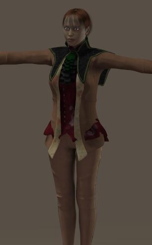
Dynamics III – 4.2 Friction

When a piece of cloth lies down on the floor or on something else, and a force – like gravity – is applied on it to drive it forward, then the contact of that cloth with the floor will work against it. Up till some limit the cloth won’t move at all, that limit is called the static friction. When that limit is exceeded it will move but will still apply a force against it. This latter is called dynamic or kinetic friction. Generally, dynamic friction is less than static. Friction is a surface quality only, it does not depend on cloth density nor on the cloth speed over the surface. It is said that rough surfaces have more friction, but that might be as well the other way around: cloth with more friction is experienced rougher. It is said that alike surfaces have more friction than surfaces which are far from similar, which is why insects can walk on vertical glass panels. It is said that surface structure from a geometrical point of view has not that much impact, friction is the result of (electrostatic) forces between the surface molecules. Take your pick. For Poser use, let’s stick to the roughness concept for the sake of it.

Total friction in green, Static portion in red, dynamic portion in blue.

An experiment the get a feel for friction is easy to do at home. Clean up a smooth long table, or a smooth plank, put a piece of cloth flat on one end and tilt the table. Until some tilt angle is reached, the cloth will stay put. That’s static friction. When the tilt becomes larger than that, the cloth starts to move smoothly. That’s dynamic friction working against the gravity pulling it down.

Poser Friction

In Poser, friction comes in various flavors:

  • Static and Dynamic between cloth element and collision object, from the collision object point of view.
    It sort of states the roughness of the surface of the collision object. These parameter values can be set in panel 2, where I manage the collision objects. Each object from the list has its own settings.
  • Static and Dynamic, from the cloth element point of view, it’s about the roughness of the cloth surface. These values can be set in panel 4, where I manage the cloth behavioral details.
  • Self-friction between cloth elements themselves, which is always about cloth surfaces.

For the moment I’ll concentrate on Static and Dynamic and leave Self-friction alone. Just leave it at 0 in the parameters panel, no harm done.

In life, friction not only depends on surface structures but also on complex interactions. Silk might do smooth and fine over glass and female bodies, but can turn in disaster when moving over plastics due to electrostatics, or when moving over brushed aluminum because the fine surface structures seem to ‘fit’.
In Poser I can define frictions for the object as well as for the cloth, but I’ve got to tell Poser which ones to use in the calculations.

If I tick the Collision Friction box in panel 4, then this particular cloth element will experience the friction as defined for each collision objects it will be sliding over.
If I uncheck the box, then all collision elements will experience the friction as defined for this piece of cloth.

So, the friction values for a specific collision object hold for the interactions with all cloth elements that will slide over it – as long as these cloth elements have their Collision Friction ticked. And the friction values for a specific cloth element hold for the interactions with all collision objects that it will slide over, when its Collision friction is not ticked. Hence, there is no combination of values that takes object roughness, cloth roughness as well as some interaction into account.
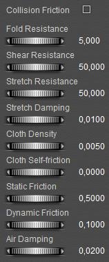
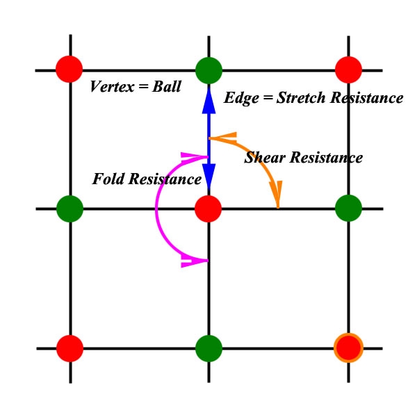
For example:
the girl in my scene wears a silk blouse and a long leatherish skirt. The skirt collides to the ground as well, which is covered with a rough carpet. For the skirt, the friction with the girl and with the ground drastically differ and I want to show that, so for the skirt I tick the Collision Friction box and I assign the girl and the carpet appropriate values, the latter substantially larger than the former. For the blouse I can’t check the box too, as the friction of silk with the body differs too much from the friction of the skirts leather with the body. So I leave the box unticked and I give the blouse its own – rather low – silky friction values.

Friction is important for cloth room. While density (gravity) and air-resistance address the interaction between the cloth and the room itself, friction addresses the interaction between the cloth and the figure it collides with. Simply stated: when the cloth vertices hit the figure in a perpendicular way we’re talking collision, and when they interact in a parallel way, we’re talking friction. So friction might be as relevant as collision. Might not be so much for still images, but it certainly plays a relevant role in believable animations using dynamic clothes.

Finding real world values

With a flattened and stretched box and a square piece of cloth, I just rebuild the “tilted plank” experiment mentioned above. And after each run of the sim, I gathered positions for the various frames in the animations. Position changes over time make velocity, velocity changes over time make acceleration.

For this acceleration a, I know that a = G*sin(z) – D*cos(z) for tilt-angle z (with the horizon, as set in Z-Rotate), for dynamic friction effect D (under investigation) and for gravity acceleration G = 9.8 m/s2 = 1.089 cm/f2 when switching to the Poser Cloth Room units cm and frames, at 30 fps. That’s basic mechanics.

The question is: how does D in this theory relate to the setting in the Poser cloth parameters?

Well, it IS the setting !! The Poser dynamic friction is not a dimensionless ratio between forces as in the physics literature, it is the resisting acceleration from the cloth on to some surface (or the other way around, in the collision object properties), under Earthy gravity, expressed in Poser Cloth Room units: cm and frames. So, when you set D to the default 0.1, the cloth on the tilted box is accelerated with 1.089*sin(z) – 0.1*cos(z), which determines its speed and displacement. Now I can appreciate why Dynamic Friction has a max on 1.0, where the critical tilting angle is about 45*. More is quite meaningless, it would lock the cloth to the object in about all positions.
Poser Cloth Density had no effect on these findings, tested from 0.001 to 0.500. As in the theory. That’s something.

When G*sin(z) – D*cos(z) < 0 the net force on the cloth is negative, and the cloth eventually would stop moving, or vice versa: doesn’t even start. At least, that’s the idea. Not starting, in formula: S>G*tan(z) introduces S for Static Friction.

I observed that the formulas did not hold very well at low cloth speeds, where Dynamic and Static frictions both became a factor of influence. This was not the case at higher cloth speeds. I observed that no value for Dynamic Friction could bring the cloth to a stand still once moving, nor could prevent it the cloth from starting to move. Only Static friction could do that. The other way around, the Static Friction parameter has no effect in the “tilted table” experiment, except for low dynamic friction (<0.1), small tilt angles (< 20*), low speeds (I sometimes needed over 3200 frames in animation / simulation). From this and the above I infer that static friction is something extra, having noticeable effects at zero or low speeds only. I can expect a minor effect from stretch, as gravity stretches the cloth, and therefore it moves the center of mass. I then guess that the Static Friction is here to prevent the entire cloth from moving as well.

In other words, it’s Static Friction at zero speed, some mixture of Static and Dynamic at low speeds (1-10 cm/frame) and Dynamic only for higher speeds. The figure intends to give some idea of this (red: static, blue: dynamic, green; total).

In the mixture, Static became noticeable only at low Dynamic values (< 0.1) or at Static values close to the critical G*tan(z) one, where it prevents the cloth from moving at all and velocities are very low.

Two issues in here, on the mixture at low speeds:

  • Determining Static friction at low speeds at low Dynamic Friction is very hard. It either requires very small tilt angles or precise observation in the few frames after the start of the cloth movement. Not very accurate, that is, and therefore all conclusions get drowned in a sea of measurement errors.
  • unfortunately, the low speed 1-10 cm/frame = 30-300cm/sec range mentioned above is the one for clothes under normal moving conditions. Girl getting seated: 60cm/sec=2cm/frame. Default cloth falling due to gravity: 245cm/sec=8cm/frame. See Density & Air Damping (previous section) and
    Cloth-the Sim Side
    on air damping and (animation) speed limits. That’s bad luck for simulating clothes. We need both the Frictions.
    When I use or analyze python scripts that address the Cloth Room, I find a parameter VelocityCutOff associated with the Frictions, set to 30. Sounds like 30cm/sec = 1 cm/frame to me. Perhaps that’s the moment Dynamic Friction kicks in.

www.hypertextbook.com/facts and a few other places on the net present acceleration and static numbers for human skin and cloth-to-cloth like info. These vary between 0.65 (skin to metal), 0.70 (skin to paper, cloth to cloth) and 0.75 (skin to plastic). Other reasonable values for Poser use (cloth, skin) ranged from 0.3 to 0.6. The latter suggests that the Poser default for Static, 0.5, is reasonable. The former suggests that the Poser default 0.1 for dynamic friction is far too low. Unless we stick to the idea that de default stand for light silk. Silk is extremely smooth, and perhaps 0.1 is fine for silk over a polished wooden table or a lacquered car surface. It does not represent normal clothing over human skin though.
Next to that there are hardly relevant numbers available for our Poser use in the literature. Lots of industrial materials, and long / heavy duty applications. Like tire rubber on concrete, like steel on steel (bolts), and so on. In general, static values are a bit higher than dynamic but not too different. Values for industrial materials can vary wildly: from 0.04 (Teflon) to over 1 (iron to iron on railroad tracks).

From the S = G*tan(z) formula, setting the angle z for a tilted plank and altering Static Friction till the cloth just did/did-not started moving revealed values for Static Friction that did not resemble any physical meaning to me.

Cloth Friction

Then I had a peek into Cloth Friction. I clothified the plank itself, put all its vertices in a choreographed group, combined both the plank and the former piece of cloth in one simulation and – of course – I checked the cloth-cloth collision box.
The first results were a nightmare, as the cloth started to wrinkle and crumble, and fell through the clothified plank. This was repaired by raising the fold-resistance (from 5 to 100).

Since then, I have not found any effect of varying this friction parameter on the position or speed of the cloth at any moment. the results are different from Static or Dynamic, but the same for all values of the Cloth friction. Some literature suggest 0.3 as a decent cloth-to-cloth value.
On top of all this, the SM page http://my.smithmicro.com/tutorials/2313.html does not show any differences between values 0.001 and 0.9, and notices that the effects will mainly be visible in animation. Well, not in mine!

So my question to you all: has anyone seen any noticeable effects in animation or stills of changes in this parameter? because if not, no investigation can be done. And then there is no need to, as any value will do for anything.

Engineering stuff

The concept of Static and Dynamic friction is sort of understood by most people: Static holds the cloth in place until the ‘driving force’ gets too large, and Dynamic works against the driving force when the cloth is moving. Both are independent of cloth density, and Dynamic friction is independent of cloth speed (unlike for instance air damping).

Wikipedia has good info on the theory, in case you need some. Friction is a force, which works against the force that drives the cloth over a surface. The friction is proportional to the force which presses the cloth onto the surface. When the surface (e.g. a plank) is tilted, the driving force from gravity reads F = d * S * g * sin(z) for density d, cloth surface S, gravity acceleration g and angle z with the horizon (flat = 0°). And the friction force reads F = f * d * S * g * cos(z) for friction parameter f (as the rest equals the force down to the box).

At the angle where static friction just prevents the cloth from moving, both forces are equal, and all collapses to f = tan(z), having most values between 0.3 and 0.6 in real nature, as I found while wading those loads of physics tables on the net. Values for f larger than 1 are rare.

For dynamic friction, we’ve got Coulombs Law stating that the force is independent of the sliding velocity.
So, when the cloth moves, we should see a constant acceleration of the cloth with gravity force F = d * S * g * sin(z) minus friction F = f * d * S * g * cos(z), over the cloth mass d*S. Hence, the acceleration reads g * [sin(z) – f*cos(z)].

For a given angle z this is like free fall along the boxes surface, so we might expect

  • falling speed v = g * [sin(z) – f*cos(z)] * t (t for time) and
  • distance s = 1/2 * g * [sin(z) – f*cos(z)] * t2.

Correcting for unit conversions, and noting that the friction parameter is a ratio between forces and therefor unit-less, we should be able to interpret the Poser measurement results. So I created an animation, 240 frames in total, and made the box rotate along the Z-axis in the first 120 frames, up till the angle of interest, say 30 degrees. I had to do this slowly, because otherwise the cloth would get launched. And it’s a good idea to zero out Air Damping to prevent hovering.

First I turned down Dynamic Friction, till its lowest 0.0001 value. Then I started playing with the Static friction, till I found the critical value that started / stopped the cloth from moving when the box was at its largest angle, and the cloth was on top. Just a fraction less and the cloth started moving. That ‘critical value’. Each angle of interest has its own critical Static Friction value, and vice versa. These were my results:

This means that at a tilt angle of 30 degrees the cloth started moving when the Static friction value came below 0.13, while physics theory says that at that angle the friction value is 0.58 (=tan(z)). So, the Static friction does not resemble anything in real life to my current knowledge. It prevents the cloth from moving indeed, not effected by Dynamic friction, but there is no relationship (discovered yet) between measured values and the literature ones. The concept fits but the model does not. So those who want to match cloth behavior to life, need a re-direction.

A similar experiment could be done for Dynamic Friction. Same setup, I took a Static Friction value a bit below the critical one, so the cloth would move but not before it had reached the top at frame 120. I varied the Dynamic Friction value and noted the frames (the time) that the cloth passed halfway and the end of the box. Higher friction values made lower speeds and therefore larger pass-by frame numbers.

After measuring the size of the box I could infer the speed, meters per frame or per second, as a result from the dynamic fraction, at that angle limit of the box. This is a shipload of details, so I’m not posting them. In the meantime, I noticed a few effects while playing with the parameters.

  • Density has no effect on friction, at the larger angles. This is physically correct. But it does have effect at the smaller angles.
  • The stiffness parameters (fold/shear/stretch) do not have effect (which is correct), until the stiffness passes values like 400.
  • In some cases with large parameter values, the cloth started rotating while coming down.

I have no physical interpretation for any of these. It might be something in the simulation algorithm. But most important, while I got neat looking results of cloth displacement over time, I could not make any physical sense out of it.

To summarize, my Poser Cloth Room experimental measurements do not fit physical theory. That’s it, plain and simple. The static friction angle vs critical value list does not follow the simple f = tan(z) or anything alike. The dynamical friction values do lead to neat distance vs time relationships, but not the one from Coulombs Law.

After a (long) while of puzzling, I finally got the message. Dynamic Friction in Poser is independent of speed and density (Poser matches theory), but it’s not a ratio between forces but a material-dependent acceleration by itself. So 1 stands for: 1 cm/frame2 which is comparable to the 1.089 of the gravity constant in Cloth Room. It won’t vary when I alter the tilting angle of the plank in the experiment. This matched my findings for higher cloth speeds (> 10 cm/frame) only. At lower speeds the effect of Dynamic Friction decreases and the results are effected by Static Friction as well. Which might be a good idea from a simulation point of view, but it’s not according to the books, and it does not help my determining of values and Poser behavior.

So, for Dynamic Friction we’ve got an acceleration D instead of the f*g*cos(z) on the plank, and units are cm and frames. Now let’s face it: when a sleeve of a shirt moves over my arm, and my arm is held under a small angle (say < 15°), the sleeve is not going to move in a way that Dynamic Friction becomes important. And when I hold my arm under a large angle, say >30°, the sleeve comes loose a bit which reduces the effect of Dynamic Friction too. This means that in practical cases where Dynamic Friction can be relevant, g*cos(z) has a value between 0.95 and 1.05 (note that g=1.089 in cm and frames). And when we allow for a range 0.90 – 1.10, we’re considering all tilt angles from 0 to 35°.

The conclusion from that is, that within a 10% accuracy, I can use the literature values (for friction constant f) for the Poser dial value D. That’s a breakthrough. And according to www.hypertextbook.com/facts and some other places on the net life values vary between 0.65 (skin to metal), 0.70 (skin to paper, cloth to cloth) and 0.75 (skin to plastic). If you find reasonable values somewhere else, you can just plug them in (and please tell me about them). Industrial values are plenty (teflon 0.04, iron-on-iron 1.0 or more, good for railroad tracks), but normal cloth over normal skin is scarce in the literature.

From this we can infer that the Poser default value 0.1 is not too bad for silk over a lacquered wooden table, but is far too low for cloth over cloth or skin. Good for Cloth Room, not too well for Clothes Room :). We might guess some values as well. Rubbing my arm with rubber eventually burns and hurts, so that’s a high value (0.85). Leather is a bit less (0.75), then comes burlap and wool (0.70), then the normal linen and cotton shirts (0.65), and then the smooth stuff, like flannel (0.55) and silk (0.50).

Static friction in Poser is entirely different from real life – as I understand it – , but we’ve got a graph now that shows theoretical and practical values in one. In literature, static friction values for cloth and skin (hardly to find, but nevertheless), ranged from 0.3 to 0.6. Similar literature however states that the Static value is a bit higher than for Dynamic, as can be expected from theory as well. Using the graph, 0.3 indicates a critical angle between 15° and 20° (red curve), which indicate a Poser value of say 0.05 (green curve). The same way, a literature value of 0.6 indicates a critical angle of about 30° which indicates a Poser value of say 0.15. And when I find a Dynamic friction (in literature) of say 0.7, and I expect the accompanying Static friction to be a bit higher (say 0.8) then this translates to a critical angle of 35°-40° and a Poser value of 0.4.

From this we can infer that the Poser default 0.5 is not too bad for cloth over a wooden table but could be reduced to say 0.35 for cloth over cloth or skin. But for smooth materials with Dynamic values as low as 0.5, the accompanying Static must be reduced to 0.15.

Another observation is that Static plays a role on moving cloth as low speeds. This is not what one expects from the books. And unfortunately, this “low speed range” (1-10 cm/frame) is very common in our clothing use of the Cloth Room. From getting seated very gracefully (0.5 cm/frame) to a speedy cartwheel (20 cm/frame), all normal animation fits in this range.

So, in order to improve image or animation results one not only has to take care of Dynamic but of Static also, while the meaning of the dial-values for both are very different. Since friction plays a relevant role in the interaction between cloth and figure, this is the place where our artistic / alien experience or gut feeling will creep in., and Real World should be considered overrated.

Finally, Cloth self-friction is a mystery to me as no change in value provides any effect on any result in animation or final image. I have no fit for even the concept.

Dynamics III – 4.3 Resistance

The Cloth Room Resistances for Fold, Shear and Stretch are determined by the fibers used, and the weave in which the fibers are combined.

The weaves – some of them shown in the next page figure – are hard to make calculations for. Fabric parameters themselves are published and available on the net, but only for the heavy duty / high performance ones. Look for fabrics for game sailing or surfing or parachutes, and you’ll find plenty. They even use different weaves for the different sails on the same ship. Look for fabrics for normal clothing, and you’ll find none. Google for “stretching jeans” and you’ll get lots of tips how to make you pants fit better. Google “folding cotton” and you’ll get a course in fancy towel folding.


http://www.bbc.co.uk/schools /gcsebitesize/design/textiles
Okay, some fiber mechanics then.Each fiber is made of some stuff that can be characterized by a Specific Weight, usually measured in grams / cm3 or the equivalent: tons (1000 kg) per m3.
Water has a value of about 1.0, Silk is 1.34

But fibers don’t come in m3. They have a thickness (diameter d) which translates to a cross-section (C= π d2/4), and a length L; their weight W = SW * C * L is expressed in tex (= grams per km) or denier (= grams per 9 km). So when SW=1 g/cm3, and C= 0.0001cm2 (=0.01 mm2, about 0.1mm thick) then the fiber will weight 10 tex (for 100,000 cm) or 90 denier (for 9 km).

The other way around, spider silk has a thickness of 3 micron = 0.003mm, good for 0.0134 tex. This implies that a fiber of 4,000,000,000cm (Earth circumference) weights only as much as 500gr. In threefold steps:

Cocoon silk = 10 micron => 0.1 tex.
Animal hair (sheep, wool) = 30 micron => 1 tex.
Cotton => 100 micron = 0.1mm => 10/15 tex (bedsheets)
T shirts do 20/30 tex.

Approximately, a m2 of fabric contains 4/3d km of fibre (thickness d in mm), so the specific weight of fabric (in gr/m2) equals 4T/3d for fiber-weight T in tex while about: d = sqrt(T/1000). For cocoon silk, this means 4*0.1/3*0.01 = 13gr/m2.

But that’s for single fiber, and usually fibers are spun into yarn, with thicker threads, thicker cloth and higher tex values. For various silk fabrics, values can be found like:

  • Gauze     12 to 20 gr/m2
  • Organza     15 to 25 gr/m2
  • Habutai      20 to 70 gr/m2
  • Chiffon      25 to 35 or 50 to 70 gr/m2 (double thickness)
  • Charmeuze     25 to 125 gr/m2
  • Crepe de Chine     50 to 70 gr/m2
  • Raw Silk    150 to 175 gr/m2

Note 1: thickness affects appearance: 10 gr/m2 is semi transparent, 25 gr/m2 is translucent, 100 gr/m2 is opaque.
Note 2: To put values in perspective: Poser default cloth density reads 0,005 gr/cm2 = 50 gr/m2.

Now we can start to pull the fiber. The result of that depends on the force per fiber-cross section, in Newton per m2, or more practical: N / mm2. But since fibers can come in various thicknesses, N/tex is the preferred material constant. And the amount of N/tex times the Specific Weight (in gr/cm3) of the material results in kN/mm2:

5 N/tex * 1.2 gr/cm3 = 5 N / ( 1 gr / 1,000,000 mm) * 1.2 gr/ 1000mm3 = 5 * 1,000,000 / 1000 * 1.2 N/mm2 = 7 kN/mm2.

At low forces, the elasticity or modulus of the material is the ratio between the stretch in % and the force in N/mm2. At high forces, a specific amount of N/mm2 will make the fibers snap. By doubling the thickness of the fiber (thread, yarn, cable) one can quadruple the strength of it.

Since measurements usually have a more scientific / engineering background instead of an industrial one, fiber strength is expressed in MPa (MegaPascal, 1 Pa = 1N/m2) or psi (pound/square inch).
1 N/mm2 = 1 MPa = 146.25 psi; 1 kpsi= 6.84 MPa.

Values for polyester (www.ides.com):

  • Specific weight (aka “gravity”): 1.24 to 1.48 g/cm3.
  • Tensile Modulus (stiffness): about 300,000 to 400,000 psi or: 3000 to 4000 psi per % elongation
    that’s 3000 to 4000/146.25 = 20 to 30 N/mm2 per % (or say 25/1000/1.25 = 0.02 N/tex)
    The breaking strength is 5000 to 9000 psi or about 35 to 60 N/mm2 which is about twice as much, so polyester is not going to stretch very much.

Steel has about a similar stiffness (20 N/mm per % elongation) and due to its high specific weight (8 g/cm3) a low 0.0025 N/tex value: you’ll get less stretch resistance per pound of material. But it stretches nicely till say 200 MPa and breaks at 400 MPa. So steel can handle far larger forces than polyester, and stretches up to 10%.
Lead for instance is much more deformable, with 1.6 N/mm2 per % elongation.

Teflon / PTFE: 2.2 gr/cm3, breaking strength 28 N/mm2; it’s a heavy, brittle material but it has an extremely low friction: 0.1 which makes it fine for surface coatings.

Another example: Kevlar (as in bullet proof vests): The modulus is about 60N/mm per % strain (twice as strong as polyester), but breaking at 2N/tex, and with a SW = 1.45 g/cm3 we get 2900 N/mm2. That’s why it’s in bullet proof vests: the projectile has to break the fibers and that slows it down considerably, it’s say 10 times stronger than steel. Human skin breaks at say 20 N/mm2 so that’s why we need the protection.

High performance cabling for shipping, like Astra: 0.97 gr/cm3 (so it floats on water), and with 0.15 – 0.20 N/tex it can handle about 150 N/mm2 while stretching only 1%. And is can stretch a lot (30% or so) while not breaking. This is the stuff that keeps ships to the quay, especially when using over 30 mm thick cables.

Generally speaking, the stiffness for high performance cabling is about 100 N/mm2 per % elongation. For most materials that we make to cover and protect our body, the stiffness is about 10. For natural clothing materials, (wool, cotton) it’s about 1. I needed tens of pages on the net to gather and combine information like the above. And I still have nothing reasonable for fabric itself, I’ll have to construct that.

1 meter of cloth required about 1000/(1.5 d) threads in one direction, and about the same in a perpendicular direction, using thread diameter d in mm. When a single thread has a stiffness S (eg 25 N/mm2 per % elongation) then 1 m of cloth has a stiffness of (1000 S)/(1.5 d)*(3 d2/4) = S*d*500 (pi rounded to 3 as the 1.5 thread distance is a quesstimate anyway).

I also stated above that 1 m2 of fabric has a weight of 4T/3d, in gr/m2, diameter d in mm, T in tex about equal to 1000 d2, so the weight in gr/m2 equals about 4.000 d/3 (d in mm). In Poser, I concluded earlier that the ratio Stretch Resistance to Cloth Density is typical for the material, an in this case it reads (S*d*500) / (4000 d/3) = 1.5 S / 4. In nature, that is say 10 and in Poser (default values) that is 50 / 0.005 = 10,000. Let’s check units again.

Assume d=1mm, then 1 m cloth takes 1000/1.5 = 667 threads, each having a 3/4 mm2 cross section. Stiffness S = 25 N/mm2 per % elongation then turns into 667 * 3/4 * 25 = 12,506 (N/mm2 per %). The amount of fiber is 2* 667 m * 3/4 mm2 = 1000 cm3, and hence weights 1340 gr (/m2). Which sounds okay, considering a 1mm thick thread resulting in a say 2mm thick cloth. The stiffness / density ratio is 12,506/1340 = 9.33 about 10.

In Poser, cloth density is not measured in gr/m2 but in gr/cm2. This makes a factor 10,000. Second, the default stretch resistance is known to produce far too elastic cloth in the simulations, 500 might do far more realistic and in line with the real values we’re using here (although it might elongate the sim itself). So, in Poser: 500 / (0.005 * 10,000) = 10 again.

In other words, the Poser Stretch Resistance is: (1.5/4 * 10,000 =) 3750 * S * D for stiffness S (in N/mm per %) as found in the literature, and cloth density D (in gr/cm2 as set in Poser). Realistic densities range from 0.025 to 0.075 despite the 0.005 default representing silk. Realistic stiffness values are:

  • Rubber        0.3 – 1
  • Natural fabric    1 – 3 (wool, cotton)
  • Enhanced    3 – 10 (cotton / polyester etc)
  • Artificial    10 – 30 (nylon, …)

A reasonable cloth value is: 4 (enhanced cotton) * 0.03 (thin shirt) * 3750 = 450. And when that turns out to be too high for a proper sim, reduce both Resistance and Density in sync.

Since shearing is meaningful for cloth only, and not for individual fibers, and has less industrial implications and applications compared to stretch, there is far less research done and there are far less values available. So my suggestion is to use values below the Stretch Resistance. Just a bit, except for those special cases that hardly stretch but shear a lot, like chain mail vests. Then Shear Resistance really is smaller than the Stretch one.

Folding has a similar story. The industry wants to know how many times a fiber can be folded before it wears out and breaks. Resistance to folding is futile. Actually, when folding a fiber with thickness d (diameter), it experiences a local stretching of 100 * d/R. 100 for making the result into %, and R is the folding radius, much larger than d.

As can be seen in the figure, the core of the fiber makes a turn forcing the outer part to relatively stretch d/2R and the inner part to shrink d/2R as well.

A sharp fold means a small R and much local stretching in the fibers. And we discussed stretching. Thicker cloth means thicker threads so d/R goes up for the same sharpness of the folds: it takes more effort to make them. Which material is a better folder? Hard to say, a better question is: which material folds sharper for the same fiber thickness and the same force applied?

Rubber seems a bad folder as it’s hard to make the folds really sharp, but what if it’s equally thick as a cotton shirt? Personally, I tend to follow the stiffness values as presented above. Rubbers fold better than natural fabrics over enhanced fabrics over artificial materials, at the same cloth (mass) density.

Since folding only affects a portion of the cloth instead of the whole cloth, using a Folding Resistance which is a tenfold smaller than the Stretch Resistance (as demonstrated in the defaults) might be a good idea.