Nodes are the essential building blocks in the Advanced interface to the Poser Material Room. They are the graphical representation of mathematical function calls, that is: calculation procedures which turn parameters (inputs) to a result (output).
Advanced
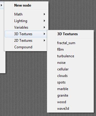
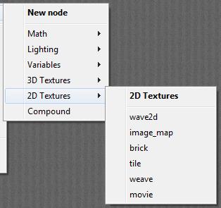
This article presents a description of the following nodes from the 3D Textures group:
- Cellular
- Spots
- Marble
- Granite
- Wood
- Wave3d
The first ones are meant to fill up solid objects with a texture that has a lot of randomness in it, the latter produce deterministic patterns, with some turbulence for a more natural effect. The previous article offers descriptions of the remaining nodes from the 3D Textures group.
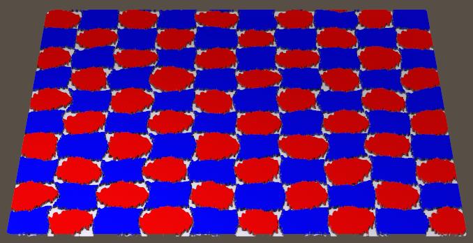
Cellular
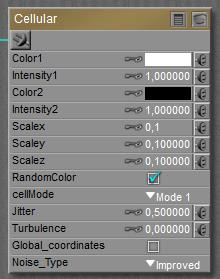
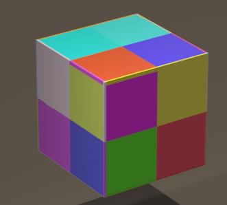
This node generates a mosaic / stained glass-like pattern. The type of pattern is defined by the CellMode parameter, the Color2 / Intensity2 defines the mortar or lead (walls of the cells) and the cells are filled with either Color1 / Intensity1, or by various colors when the RandomColor option is checked.
Larger ScaleX/Y/Z values make larger patterns (so these work opposite to the scale parameters of the previous nodes).
So what do the various (Cell)Modes do?
Mode 1 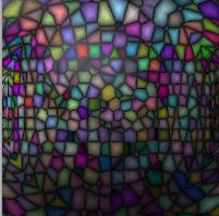 |
Mode 2 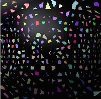 |
Mode 3 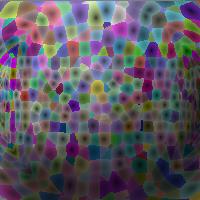 |
Mode 4 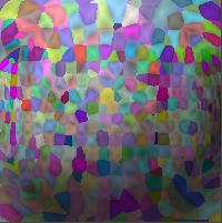 |
Mode 5 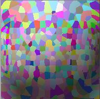 |
In all modes the cell patterns are similar, but the use of the “mortar” is different. Mode 1 makes nice stained-glass while Mode 2 might be nice for granites. Mode 3 and 4 use the mortar to make the structure visible in an indirect way, while Mode 5 does not apply any mortar at all. That means that this mode gives me a homogeneous fill with Color1 when the RandomColor is OFF.
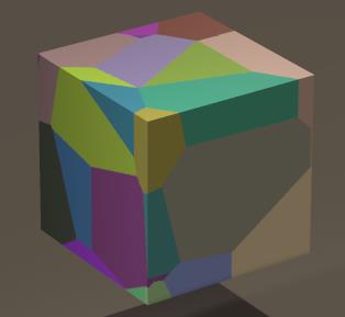
Do note that the texture is a 3D one, it’s continuous in all spatial directions, and mesh edges are irrelevant.
This however depends somewhat on Jitter, which controls cell-irregularity. The left render above was made with Jitter=1, the right one with Jitter=0.
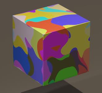 Low Turbulence makes straight cell edges, high values make curves ones. The right image above with Jitter=0, Turbulence=0 changes to …
when only Turbulence is raised to 1.
Noise_Type lets me pick my favorite random number generator behind all the irregularities, and the Global_Coordinates option determines whether the pattern is relative to the object (OFF) or to the Poser space (ON). The latter is relevant when multiple objects make up one ‘thing’ and the material has to be continuous over all of them. Note that this also implies that the pattern changes when the object is moved around in an animation, so it’s meant for inanimate objects in the scene.
Spots
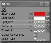
Spots create the kind of pattern I get when pouring red paint (Base_color) into a bucked with white (Spot_color), though I can alter the colors of course. To me the naming of the colors seems a bit in reverse given the result below, but anyway.
 makes
makes 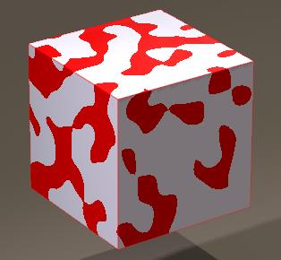
Threshold defines the Base to Spot ratio: a low value (down to 0.0) gives more white (Spots) and a high value (up to 1.0) gives more red (Base).
 Softness defines the blur at the edges, at 0 the edges are well defined (image above) and higher values makes the impression that I have been stirring the mix. With 0.4 I get…
Larger Spot_Sizes make larger spots (no surprise there) and as discussed at the other nodes above, Noise_Type lets me pick my favorite random number generator behind all the irregularities, and the Global_Coordinates option determines whether the pattern is relative to the object (OFF) or to the Poser space (ON).
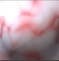
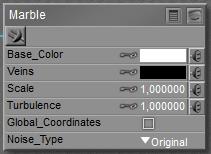
Marble
No doubt I can guess the use of this one, but… what’s a proper marble pattern? As
 makes
makes 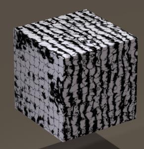
I see thick veins in one (X-) direction, and thin veins in the two other (Y, Z) directions. Larger Scales make larger patterns, Turbulence makes them wilder, and as discussed at the other nodes above, Noise_Type lets me pick my favorite random number generator behind all the irregularities, and the Global_Coordinates option determines whether the pattern is relative to the object (OFF) or to the Poser space (ON).
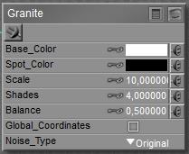
Granite
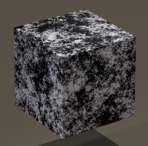
A no-brainer again, but what makes a granite pattern? It’s sort of various kinds of gravel mixed with clay and squeezed together into one material, so
 makes
makes 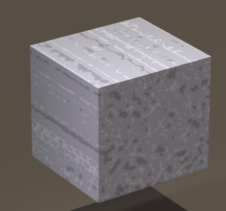
Larger Scales make larger patterns, note that the value is increased (from default 1) to 10 to get the granite effect visible. It’s a bit like the Cellular node in Mode 2, with variants of the same (Spot) color. Shades determines the amount of colors in the granite, while a low Balance pushes the colors towards the Spot_color, and a high value pushes the colors towards the Base.
As discussed at the other nodes above, Noise_Type lets me pick my favorite random number generator behind all the irregularities, and the Global_Coordinates option determines whether the pattern is relative to the object (OFF) or to the Poser space (ON).
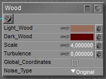
Wood
Another no-brainer, which indeed makes the ring-patterns I expect.
 makes
makes 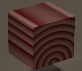
Larger Scales make larger patterns, and some Turbulence make them less regular and hence more natural. As discussed at the other nodes above, Noise_Type lets me pick my favorite random number generator behind all the irregularities, and the Global_Coordinates option determines whether the pattern is relative to the object (OFF) or to the Poser space (ON).
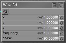
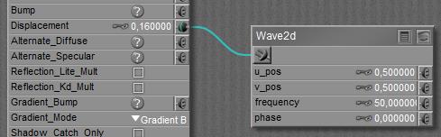
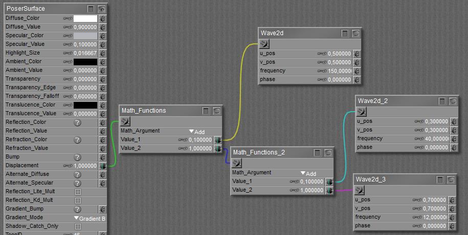
Wave3D
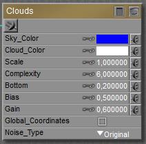
This is the 3D spatial equivalent of the 2D surface wave. In 3D, it’s like a sound blast, with alternating high (white) and low (black) pressure areas.
 makes
makes 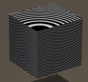
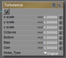
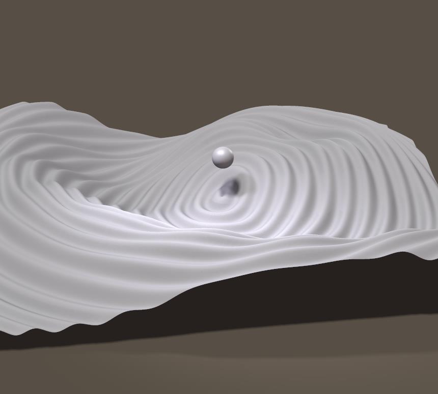
The X,Y,Z parameters do NOT scale the pattern, but move the center around instead. Higher Frequencies make smaller patterns, and more frequent repetitions in the same area. Phase caters for the alternating state, and is quite valuable in animation.
The pattern is in Global Coordinates and ripples through when the object is moved around.
I’m sure one can find an artistic purpose for texturing with this node. Using it as a density driver in the Poser Atmosphere can make the sound-blast patterns visible in a room (vibrating smoke).
Next >
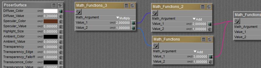
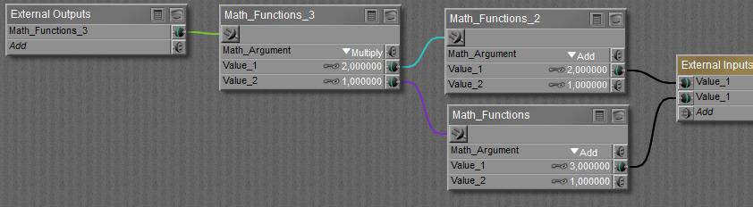
 button), and I can build a complete structure between the final node containing all External Outputs (left in the scheme below) and External Inputs (right in the scheme).
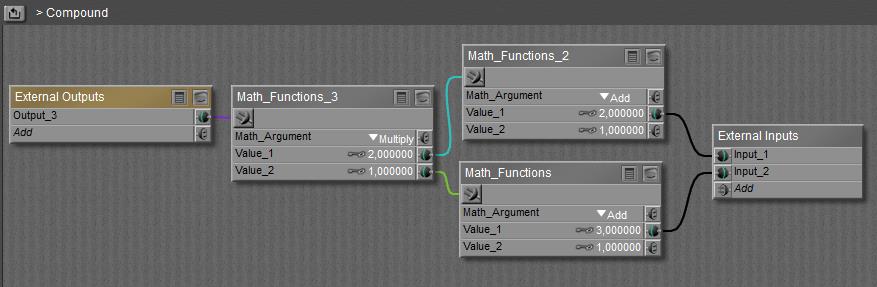
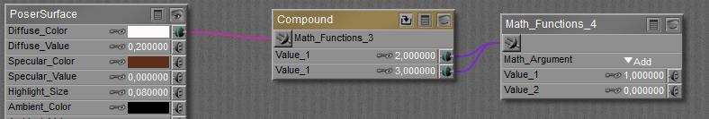
 When done building the node can be collapsed (the
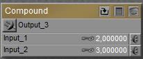
  button) and will just show the outputs and inputs defined in the Material Room definition area:
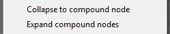
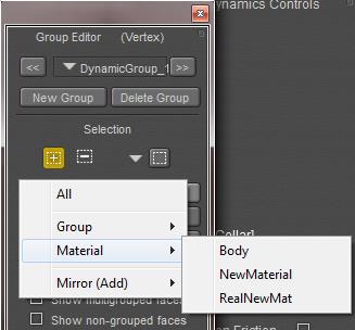
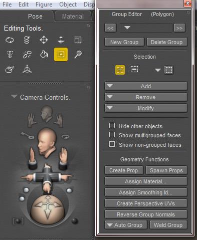 In Poser, groups are managed via the Group Editor, accessible via the Grouping Tool icon in the Editing Tools palette. The Group Editor takes a serious portion of the Figures and Props Editors chapter in the Poser Reference Manual, and reading this carefully before use is much recommended as the tool is quite powerful and can have drastic effects on the behavior of objects it’s applied to.
 or
or 
 makes
makes 
 makes
makes 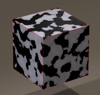
 makes
makes 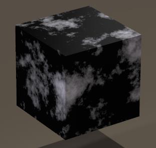
 to 1.0
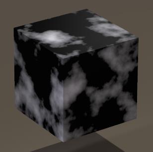
 makes
makes 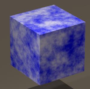
 makes
makes 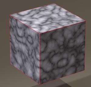
 makes
makes 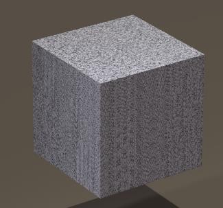
 Advanced
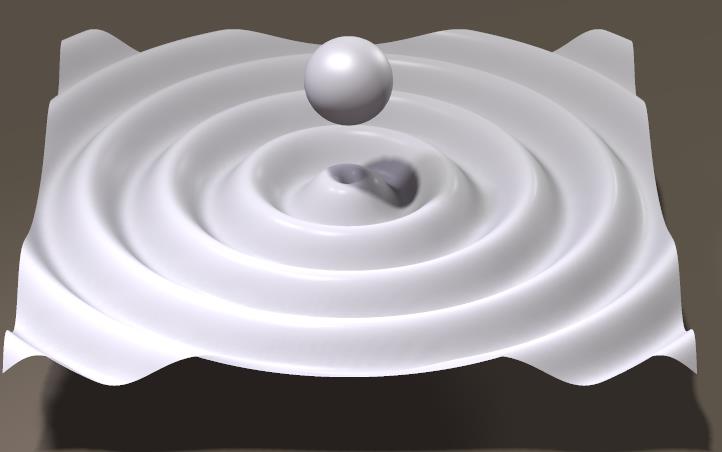
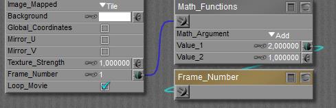
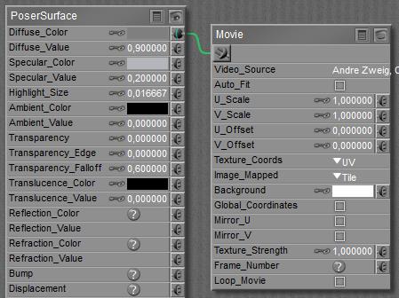 In the Advanced interface to the Poser Material Room, nodes are the essential building blocks. They are the graphical representation of mathematical function calls, calculation procedures turning parameters (inputs) to a result (output). For applying movies, the Movie node can be found in the 2D Textures group, and reads like …