Although various configurations can be setup via Material Room menus, and can be managed through the Simple interface, this topic is considered Intermediate level.
Intermediate
Each object in the Poser scene is a mesh, consisting of vertices, and polygons defined as ordered groups of vertices; usually three (tri geometry), or four (quads). On one hand, an object mesh even can be formed by multiple submeshes declared to be one, even when they are not connected. On the other hand, a single continuous (sub)mesh can have its vertices and/or polygons organized into groups.
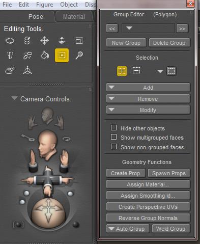 In Poser, groups are managed via the Group Editor, accessible via the Grouping Tool icon in the Editing Tools palette. The Group Editor takes a serious portion of the Figures and Props Editors chapter in the Poser Reference Manual, and reading this carefully before use is much recommended as the tool is quite powerful and can have drastic effects on the behavior of objects it’s applied to.
The tool can be used in various ways:
- To select polygons, and duplicate those into a prop. For instance: select portions of the head into a new Mask prop.
- To group polygons into Body Parts, this in turn can be affected by the bones of a figures skeleton. Those bones turn a prop into an animatable figure; this grouping is done from the Setup Room.
- To group polygons into Material Groups or Zones. See below.
- To group polygons into Hair Groups, this is done from the Hair Room. Those are the areas I can grow hair on, and apply the dynamics of wind and gravity to, according to my requirements. In http://www.book.artbeeweb.nl/book-poser/hair-room/ you can find some Hair Room tutorials to start with.
- To group vertices into Cloth Groups, this is done from the Cloth Room. Those are the areas I can apply the dynamics of body moves, wind and gravity to, according to my requirements. In http://www.book.artbeeweb.nl/book-poser/cloth-room/ you can find some Cloth Room tutorials to start with.
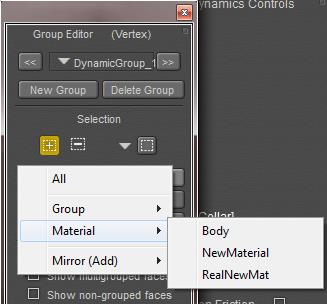
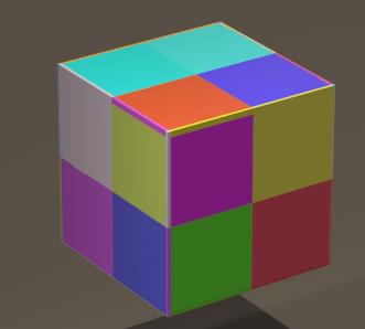
Material Zones
When I’m in the Group Editor, and I have selected / created a (Body Part) group of polygons, and I click the [ Assign Material.. ] button, I can either enter a new material name, or select an existing one from the list.
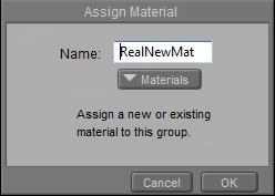 or
or 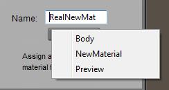
Note: in Cloth Room, the Group Editor works on vertices instead of polygons. Therefore, new material groups cannot be defined from there. The button just will not respond.
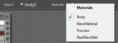
Then, from Material Room, I can define a material definition for that (Materials) zone:
But also, those Material Zones are available for defining and refining selections in groupings elsewhere (via the [Add] or [Remove] buttons). So, all vertices or polys from a Material Zone can be assigned specific dynamic properties in Cloth Room. This way, I can make portions of a dress not only look like leather or lace, but also behave as such.
And via Hair Room, I can make long and short fur or hair, both having different dynamic behavior and different colors (via Material Room) as well, by using the same groupings.
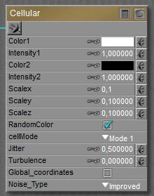
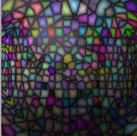
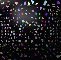
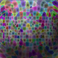
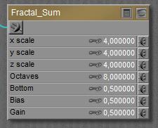
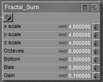
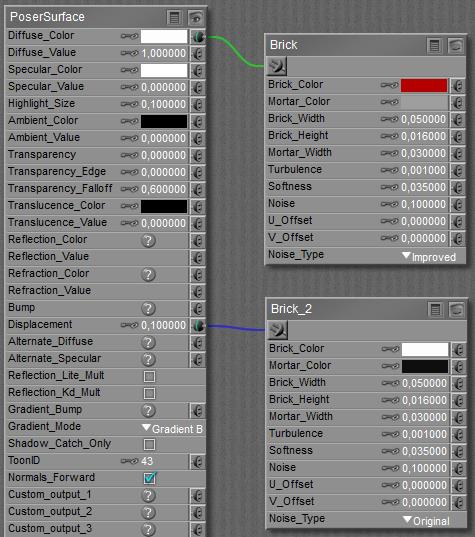
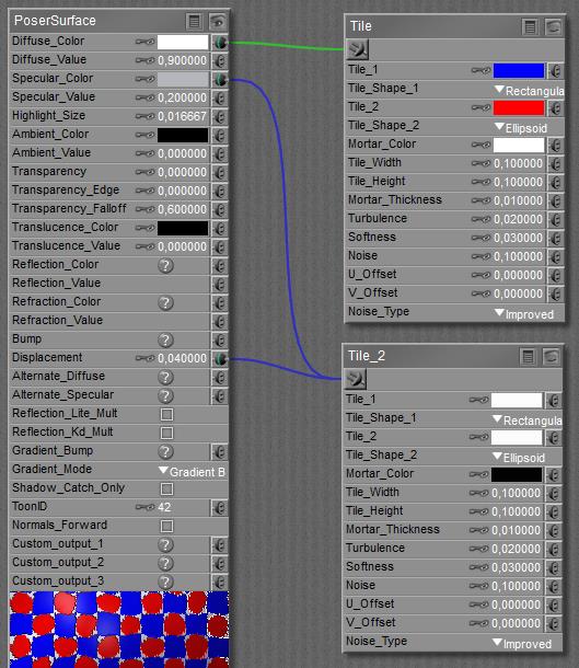
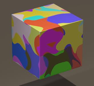 Low Turbulence makes straight cell edges, high values make curves ones. The right image above with Jitter=0, Turbulence=0 changes to …
 makes
makes 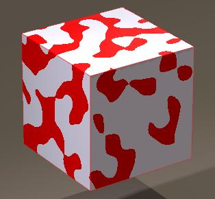
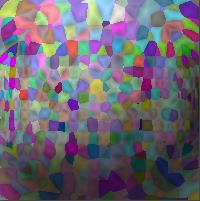
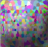
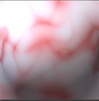 Softness defines the blur at the edges, at 0 the edges are well defined (image above) and higher values makes the impression that I have been stirring the mix. With 0.4 I get…
 makes
makes 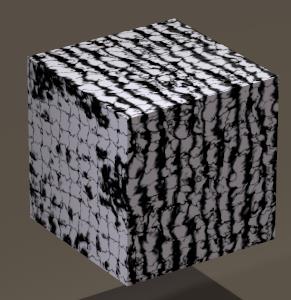
 makes
makes 
 makes
makes 
 makes
makes 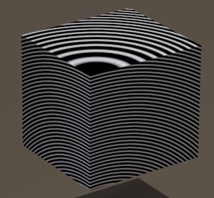
 makes
makes 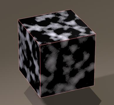
 makes
makes 
 makes
makes 
 to 1.0
 makes
makes 
 makes
makes 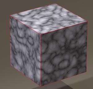
 makes
makes 
 Advanced
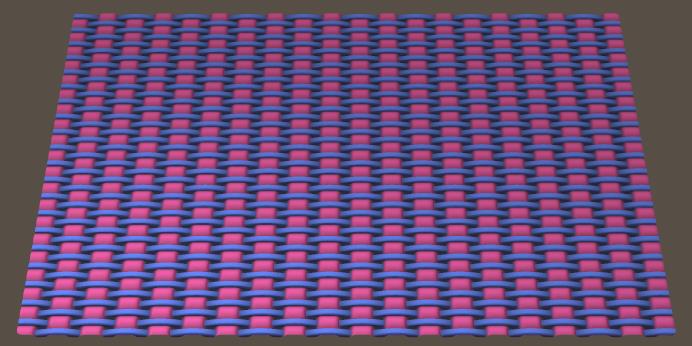
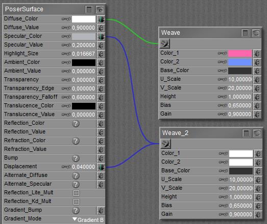
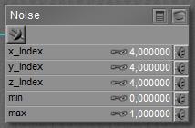
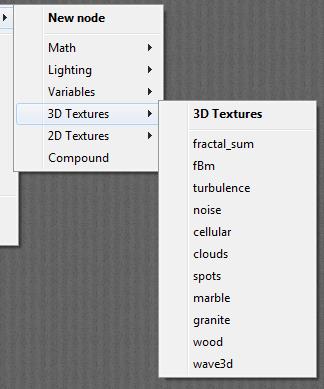
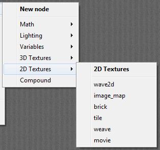
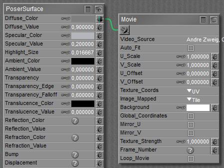 In the Advanced interface to the Poser Material Room, nodes are the essential building blocks. They are the graphical representation of mathematical function calls, calculation procedures turning parameters (inputs) to a result (output). For applying movies, the Movie node can be found in the 2D Textures group, and reads like …
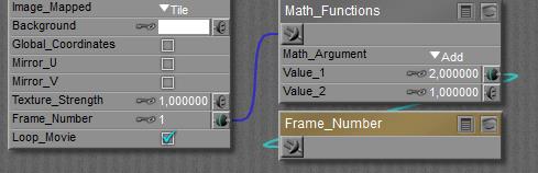
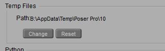
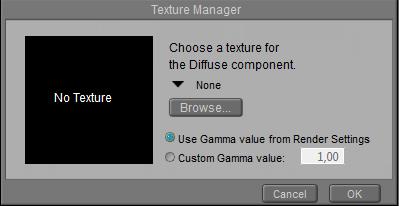
 More handling details are managed through the Render tab in General Preferences
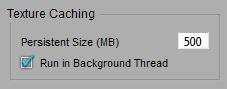
 The Texture Cache is filled up while building the scene and rendering, and cleared when Poser exits (in a regular way). Except for the <so many> MB’s of most recently added images. This way, some translation is avoided when I reopen Poser to continue my work on the same scene. This Persistent Size can be set as well.
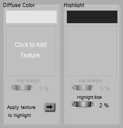 =>
=> 
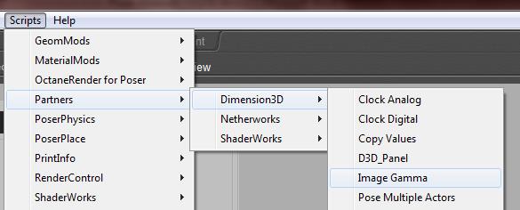
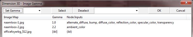
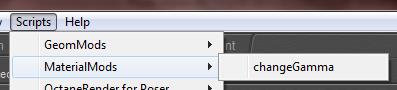 When I already have various images in my scene, and when I do not want to recheck and reset all of them, Poser can help me with various scripts:
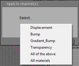
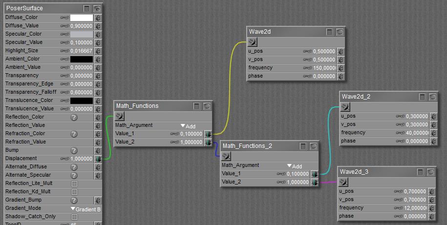
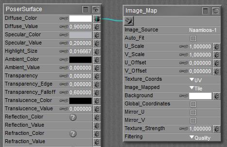 In the Advanced interface to the Poser Material Room, nodes are the essential building blocks. They are the graphical representation of mathematical function calls, calculation procedures turning parameters (inputs) to a result (output).