Nodes are the essential building blocks in the Advanced interface to the Poser Material Room. They are the graphical representation of mathematical function calls, that is: calculation procedures which turn parameters (inputs) to a result (output).
Intermediate
Abstractly spoken, any object surface is the separation of two volumes: the ‘inside’ part and the ‘outside’ part relative to the object. When both parts are transparent to some extent, a light ray can pass through the surface. And when both parts consist of different stuff, with a different ‘optical density’ (like air and water, water and glass, …) then the light ray gets bend at the surface because the speed of light is different at both sides.
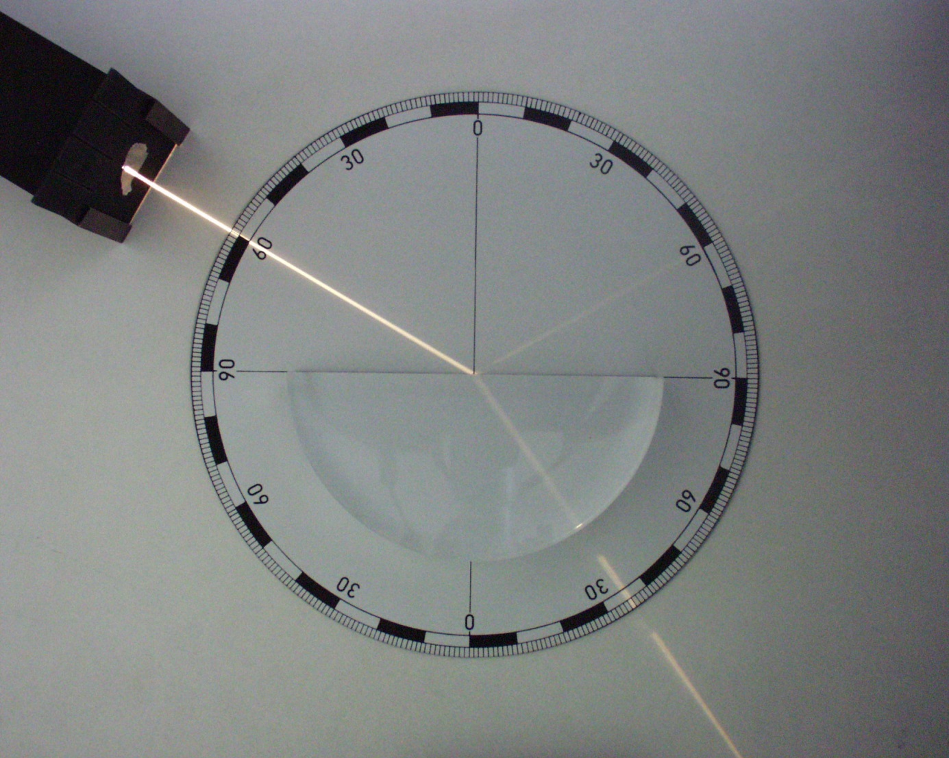
This is ‘refraction’, and by inventing an Index of Refraction (IOR), being 1.0 for vacuum, each material can have its own value defining its optical properties. In other words, the IOR defines the amount of refraction, the extent of light ray-bending, at the surface.
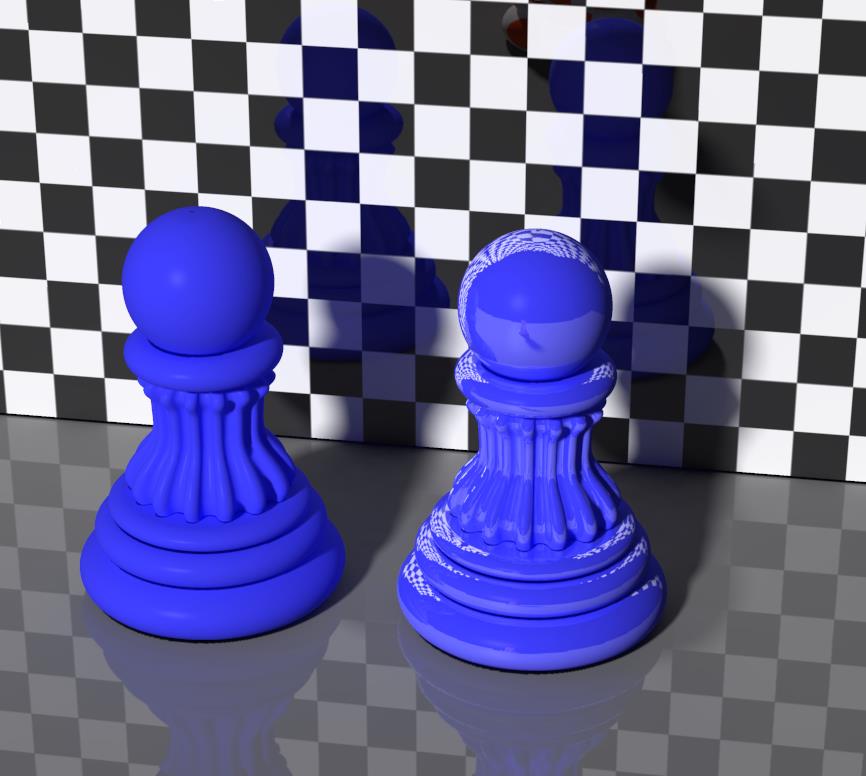
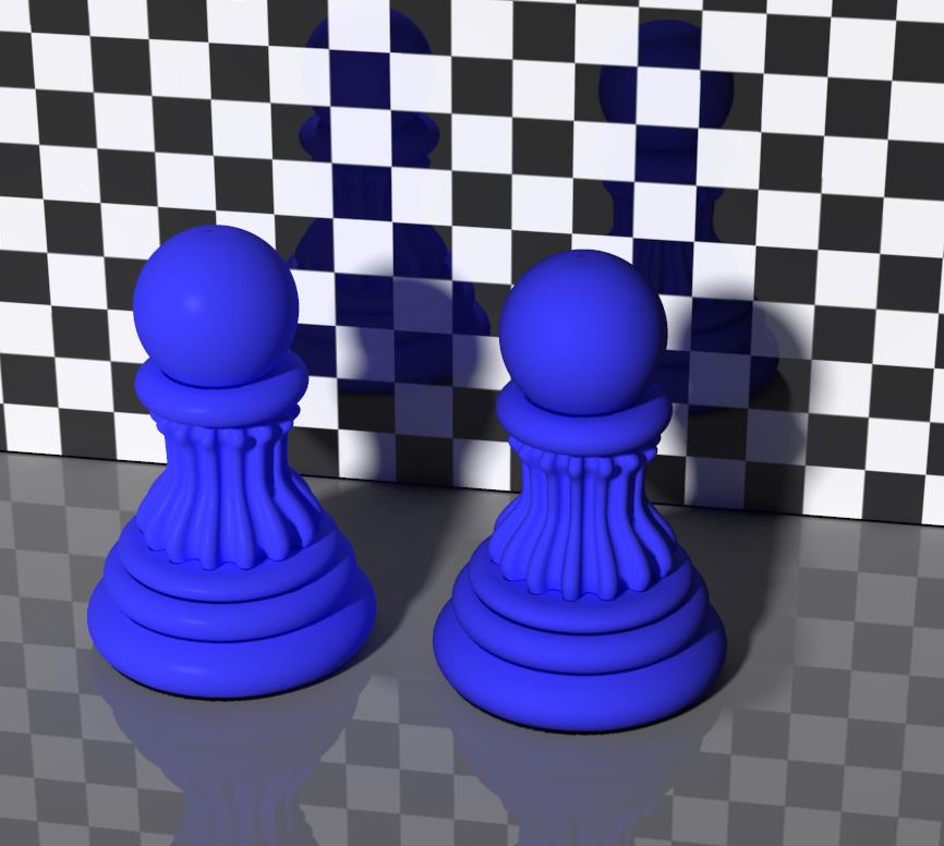
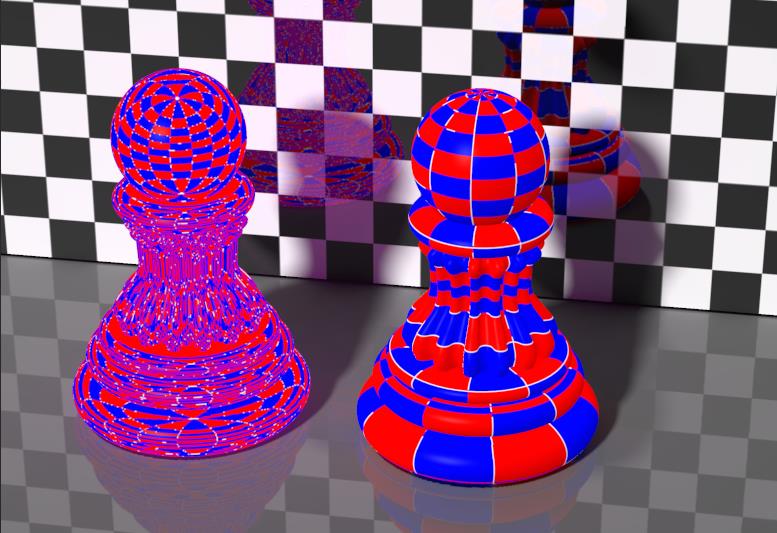
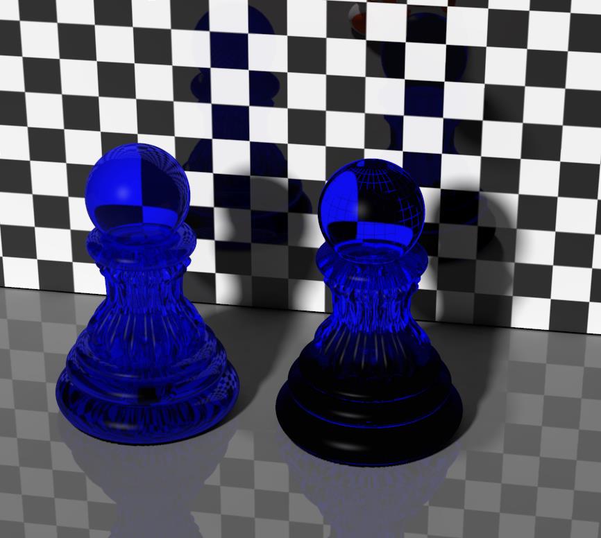
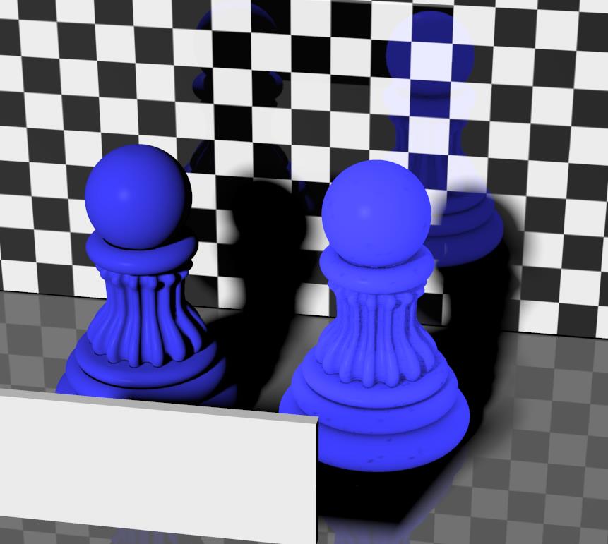
The image below illustrates transparency without refraction (left pawn) and refraction without transparency (right pawn). Without refraction the background image passes through undeformed, with refraction the pawn shows a glass-like behavior. As I can see, Poser refraction takes care of transparency all by itself (*).
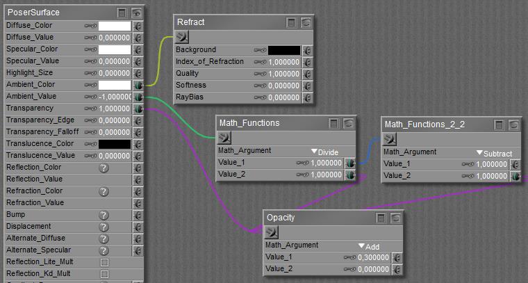
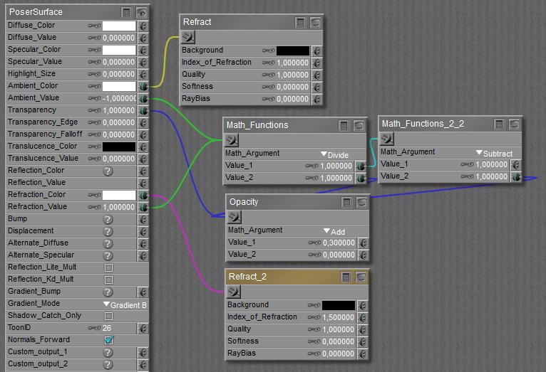
This Refract node adds accurate (*), raytraced refraction to the PoserSurface material definition. It requires Raytracing in Render Settings to be switched ON. The quality of the result depends on the ‘Number of Bounces’ set in Render Settings as well. Passing through a surfaces counts as a bounce, so entering and leaving a transparent object requires two bounces. The number set is a maximum value, when Poser does not need them it won’t use them, but if the number of bounces for a light ray exceeds this limit, the light ray is killed. This might speed up the rendering while it also might introduce artifacts (black spots) in the result. The tradeoff is mine, but as nature has an infinite number of bounces, the max value is the best when I can afford it.
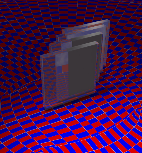
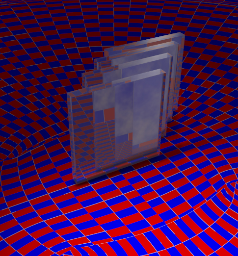
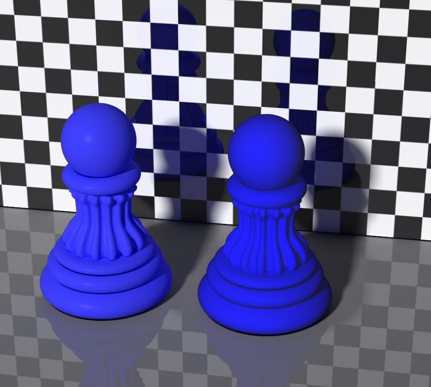
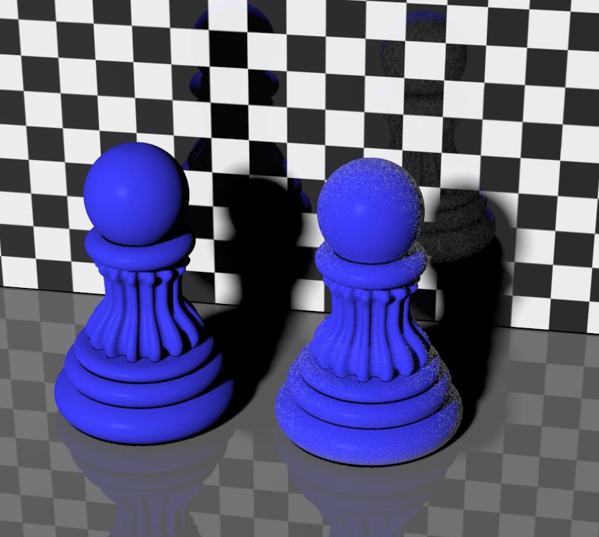
Left: Raytrace bounces set to 4, while 4 objects require 8 bounces. Right: When the value is increased to 8 or more, all objects and surfaces can be passed.
(*) Notes:
- Refraction only handles the light from objects in the surrounding scene. It does not cater for the rays from direct light sources (spot, point, etc. lights), these will not get bend at all. Refraction does not work for light passing through an object shining onto another object: refractive objects behave opaque to direct light and make deep shadows accordingly. But Transparency behaves as expected, as discussed in other basic and advanced articles. In other words: basically Poser transparency and refraction are supposed NOT to be mixed, but in various cases you’ll need to. Mixing them will introduce a lot of issues, including a serious slowdown of rendering.
- At the moment (Poser versions up till Poser 10 / Pro 2014 SR3) raytraced refraction is in error, as the ray leaving the object towards the camera is bend the wrong way. In real life, a light ray should bent ‘forward’ when entering the object, ‘backward’ again when leaving he object, and as a result it should continue its journey parallel to its original path but just shifted in space. Currently in Poser the ray bends in the same direction twice. It’s said to be repaired in Service Release SR4.
Practical use
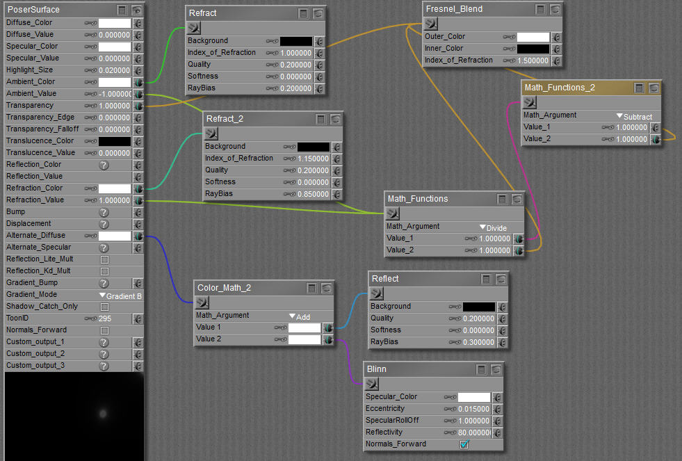
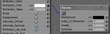
I want to use refraction when a material represents liquid or glass, but in real life such transparent materials are reflective as well. And actually, those two phenomena are in a complex balance: the more refractive a material, the more reflective it will be too. On top of that, real life transparency and reflectivity both depend on the angle the camera looks at the surface. The skewer the angle, the more reflective the surface becomes, and the less light is left to pass through. That makes the surface less transparent (and not: less refractive, the bends will be the same). These combined issues are knows as the “Fresnel effect”, and supported in Poser by the Fresnel node and the Fresnel_Blend node.

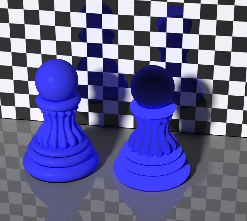
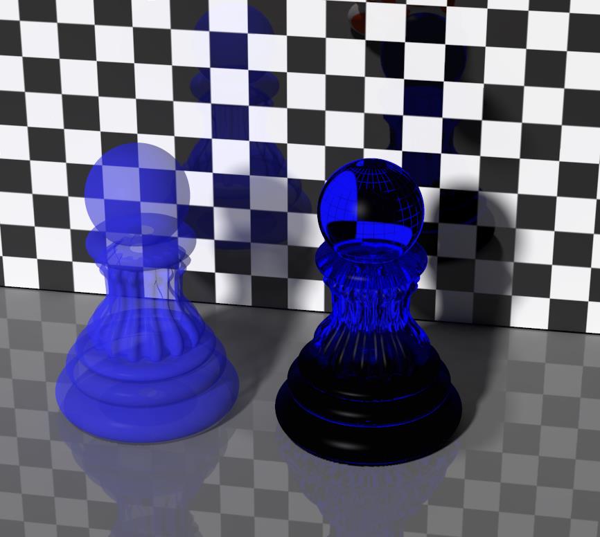
The right pawn still shows refraction as before, the left pawn shows Fresnel. Especially the upper edge of the left pawn clearly shows that Fresnel is not only transmitting the wall at its back, but also is reflecting it. Those reflections are missing on the right pawn.
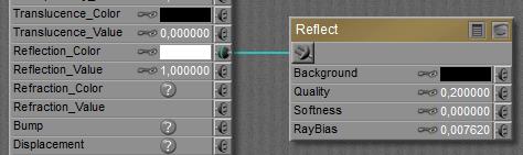
About the Refract node parameters:
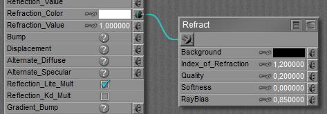
The Index Of Refraction is discussed above. Values for various materials can be found here.
Quality offers a tradeoff between speed and result; high values require longer render times but present crispier results. Softness increases the blur of the refracted image, representing irregularities, impurities and even minor movements and vibrations in the refracting surface.
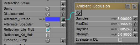
RayBias is a special feature to address a special issue, regarding the refraction on image-based displaced surfaces. RayBias is a distance, in the Poser units as set in my User Interface preferences. The default is 0.3 inch or 0.007620 meters as in the screen grab above. Poser takes the refracting surface, moves it for this distance outwards from the object, then it calculates the refractions, and then it projects those refractions onto the surface of the object itself. This way, all irregularities of the refracting surface which are smaller than this distance are disregarded, usually these are caused by the details of displacement maps. It speeds up refraction calculations considerably, but it does introduce artifacts and less accurate refractions as a downside. For that reason, one should not have this value larger than the amount of displacement in the same PoserSurface material definition. The 0.3” (0.76cm) default value is quite a lot, actually.
Refraction Color (in the PoserSurface column) gives color to the material, like red to wine or sapphire. But do note that this is a surface effect only, like a colored plastic cover around the object. Poser cannot do volumetrics, the wine will be equally red whatever way I look at it, and the glass will be equally red whatever the thickness.
The contribution of refraction to the total surface definition will be made up from the combination of Refraction_Color * Refraction_Value. This does not hold for the refractive effect itself, which is determined by the IoR. To represent a dark colored material, I can either use a dark color in the swatch, or a low value. Note that Color will be affected by Gamma Correction, the Value will not so 80% White and 100% Value will behave different from 100% White and 80% Value under GC render conditions. For that reason, it’s recommended to leave Value at 1.0 and put all adjustments into the color swatch.
Rendering
Raytraced refractions and reflections are realistic, detailed, and although Poser performs them quite efficient they are time and resource consuming at render time. As a consequence, one should be careful not to put too many raytracing intensive challenges into one scene. InDirect Lighting (IDL) is such a challenge, having a lot of reflective and/or refractive surfaces in one scene is a challenge, having reflections and refraction (and especially Fresnel) on a complex surface is a challenge, and having Max Bounces (and the IDL Quality options) set high in Render Settings make a challenge as well. Take the Refraction vs Fresnel image shown above. It’s IDL, and reflective wall and floor, and quite high values in Render Settings. Rendering on a fast machine took 3.5 hours. Poser does have its limitations. There are no meaningful fast alternatives for refraction, like we have image-maps or environmental maps for reflections. Sorry for that.
On top of all those things, Poser raytracing is designed to work with a completely non-transparent surface; refraction caters for (full) transparency on its own. While doing so, raytracing works for objects in the scene only, it cannot handle direct light, nor the shadows or specularity thereof. Mixing raytracing with transparency however might produce unexpected or even erroneous results, while also taking render time to infinity.
Next >
 As said, instead of using the node on a surface, the use of the light property is preferred.