The short answer is NO, and be advised that there are a lot of contrasting opinions in the forums and around on the Internet. Some opinions are presented as religion, and their advocates act as true evangelists. Others are more relaxed. What does it matter?
Well, 3D programs like Poser are very feature rich, and far from easy to comprehend fully (at least to me). And finally, I need a “way of thinking” to use those programs effectively and efficiently. That is: for establishing a specific effect in my result, I want to get a good way to accomplish that, without wasting a lot of time (and other resources) on thinking it up, implementing it, testing, fine-tuning and rendering. The best “way of thinking” for me depends on my background (experience, interests, education, expertise) and the kind of effect and result I want to accomplish. Stylish results for comics have different requirements from studies for oil-painting or crayon-drawing, from product-casing, from animation or from photoreal’ish rendering, either for web-galleries or for large scale fine print.
So in some cases the “let’s not add up to 100%” approach is good enough, in other cases people might prefer a complete Master of Physics approach, or anything in between. It’s good to have all those variants around, and to add some of them to a personal toolbox.
More in detail
Various opinions arise from the limitations on materials in nature, when a single source of light hits a surface. That light can be reflected, diffused, transmitted and so on, and hence these portions should not add up to a value larger than one (100%). It could be less, to represent absorption in the material. However, the various portions of a Poser material respond to quite different – and quite independent – sources of light. This is presented in a basic way. And there are various practical considerations to be taken into account.
Intermediate
For a better understanding, let’s review the situation for direct lighting and for indirect lighting separately. In both cases, Bump and Displacement, as well as Transparency and Refraction will only affect the distribution (and eventual reduction) of light re-emitted by the object towards the camera into the render, but will certainly not increase the amount of it. So these aspects can be ignored for the moment.
For the sake of simplicity, let’s first consider a single (direct, point) source lighting an object in the midst of a scene, under non-IDL conditions:
Direct Lighting only
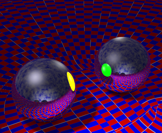
The diffuse portion of the light will be re-emitted by the Diffuse portion of the material, while the specular portion of the light will be re-emitted by the Specular part of the material, emulating the reflection of the direct light source (the lamp) itself. The Reflection part of the material will bounce the diffuse and specular results from the light source via other objects in the scene onto the object surface (unless a reflection-map is used to fake the effect).
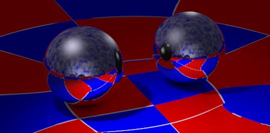
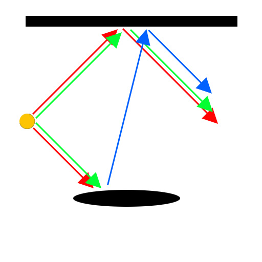 Red: direct diffuse light into scene and onto object, resulting in general visibility Green: direct specular light into scene and onto object, resulting in highlights= reflection of lamp Blue: visibility and highlights combined from the scene reflected onto object = reflection of scene
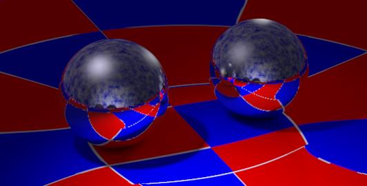
Note again: the reflective surface of the reflecting object not only does not reflect the direct light source itself (as a lamp is not considered an object at all), it does not reflect the light rays either. So I cannot use a flashlight and a mirror to illuminate an object around the corner.
Since Reflection and Specular both represent the same reflective properties of the material for just different sources of light, they should be balanced somewhat for the objects surface. This effectively means I’m balancing the visibility of the lamp with the visibility of the scene objects, both onto the surface of the object at hand. And – for that same object surface – I’ll have to balance its Reflection / Specular at one hand to its Diffuse at the other hand, to make a neat impression of the objects reflectivity as such, despite the fact that the sources of the lighting are different.
On top of this, the material can offer some glow of its own, in the Ambient or Translucence channel (*). This will wash out some surface details of the object, and will just add to the light re-emitted from the surface by Diffuse, Specular and Reflection.
InDirect Lighting conditions
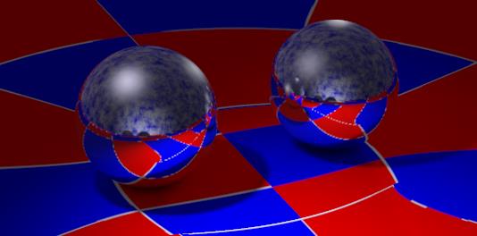
Second, let’s switch on IDL conditions. Now all the light (diffuse, specular, reflections, ambient glow, etc.) re-emitted by any object in the scene works as a diffuse light onto the object (and all other objects) as well, in addition to the already available direct lighting. Effectively, this will turn up the diffuse lighting level seriously. Not only will this turn my render into an overlit one unless I lose a few lights and turn down the intensities of others, it will also distort the balances between the material portions sensitive to direct light (Diffuse, Reflection), and the portions which are not (Specular, Ambient).
For Specular, this implies that we either have to re-balance this property against Reflection and Diffuse, or we have to rebalance the specular properties of the available direct lights against the new IDL-based lighting level. The latter part might take far less effort, especially in material-rich and/or crowded scenes.
To complete our understanding on Reflection, let’s re-consider the use of a flashlight, shining on a mirror in an attempt to illuminate an object ‘around the corner’. The (direct) flashlight will produce a bright spot from diffuse and specular on the mirrors surface. Under IDL conditions, this spot will act as a diffuse light source, shining all around creating some extra illumination ‘around the corner’. There still will be no defined bundle, though.
For Ambient/Translucency (*), the hotspots (led-lights or so) on the object might need to glow a bit more to be seen within the altered IDL lighting level.
(*) Ambient and Translucence are equivalent parts in the material definition. Just use either one or the other. The main difference is that Ambient is supported by the Simple interface, and by most exports to non-Poser file formats and renderers, while Translucence is not.
Next >
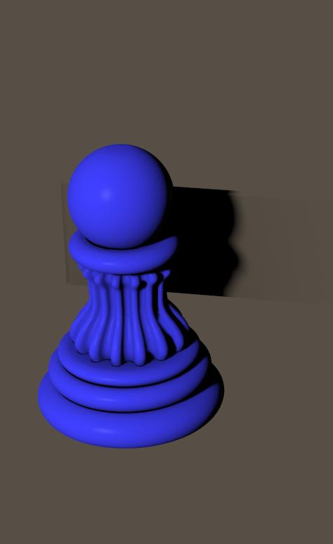
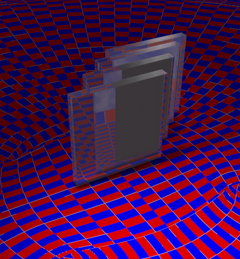
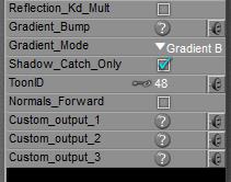 By switching ON the Shadow Catch Only option in a PoserSurface definition the surface will disappear completely, except from the shadows cast from other objects, and from itself as well.
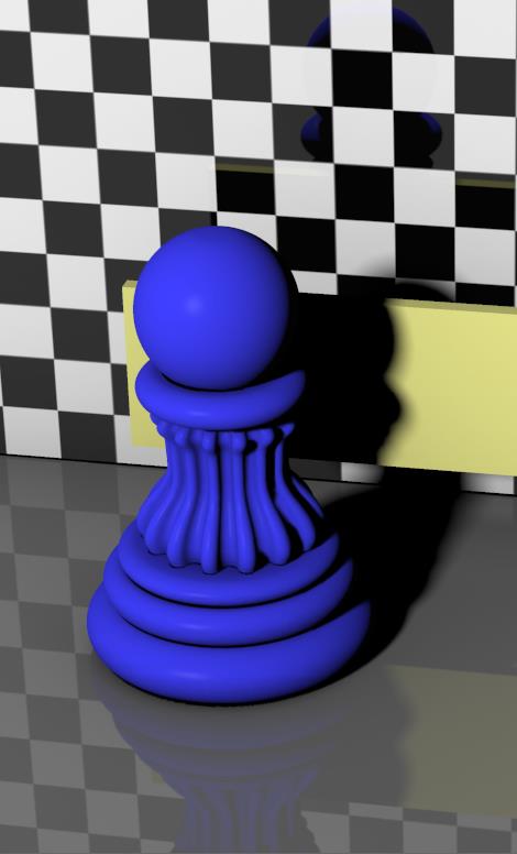 =>
=> 
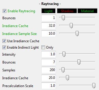 To some extent, InDirect Lighting (IDL) is an application of reflection. Light hitting objects is diffused back into the scene, hitting other objects and so on. At each bounce the ray dies a bit, and after so many bounces it gets killed if it happens to be still around anyway. In open scenes a ray might get lost into open space, but most scenes applying IDL are encapsulated within a dome. Then killing rays really reduces the amount of rays around, and hence reduce the lighting level.
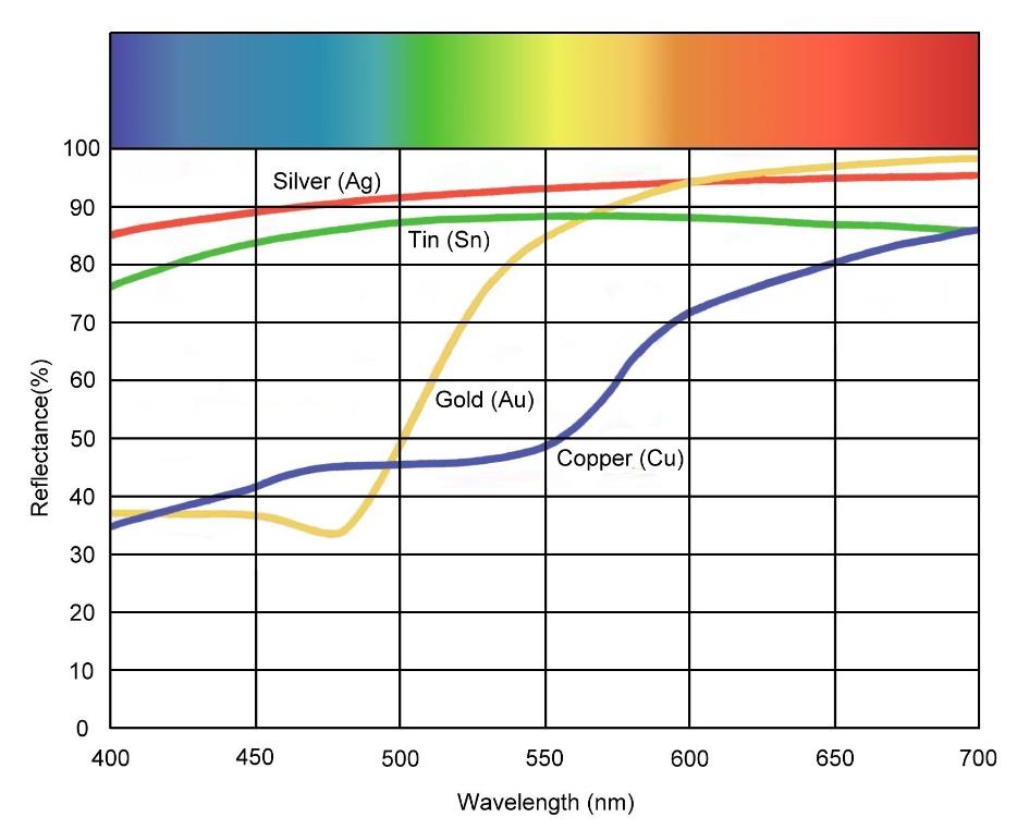
 .
.
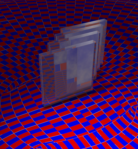
 Option ON
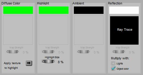 or
or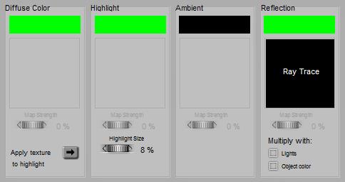
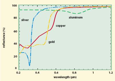
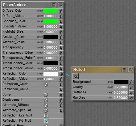
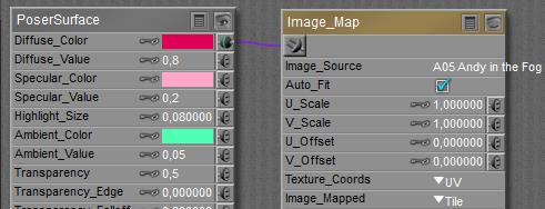
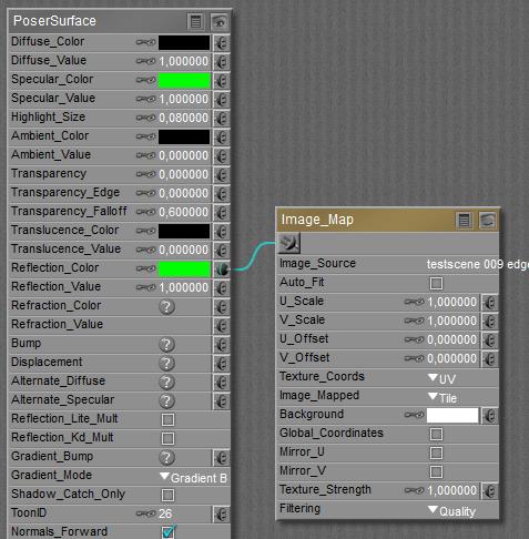 Formally, metals have a high reflectivity and no diffuse. Ensure that there is always something to reflect, then, using Raytrace (above) or an image (below). As there is no Diffuse, do not multiply with it!
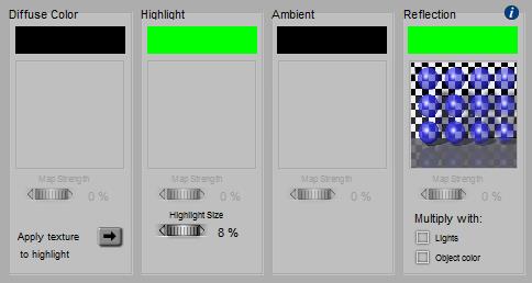 or
or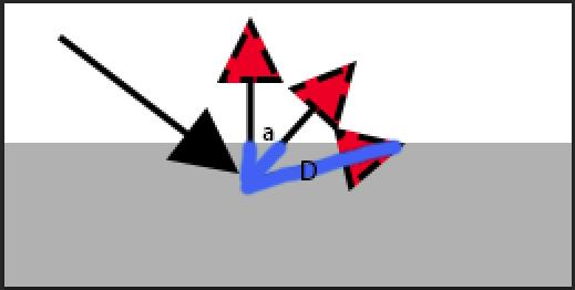 As this distance D is inversely proportional to the cosine of the exiting angle (D=D0/cos(a)), the intensity of the diffuse light in that direction will be proportional: I = I0 cos(a). This is the angular distribution of outgoing, diffuse light, according to the mathematician J.H. Lambert (about 1750). At perpendicular scattering, angle a=0 so cos(a)=1 and the response is maximal, while at parallel scattering cos(a)=0 and there is no response at all.
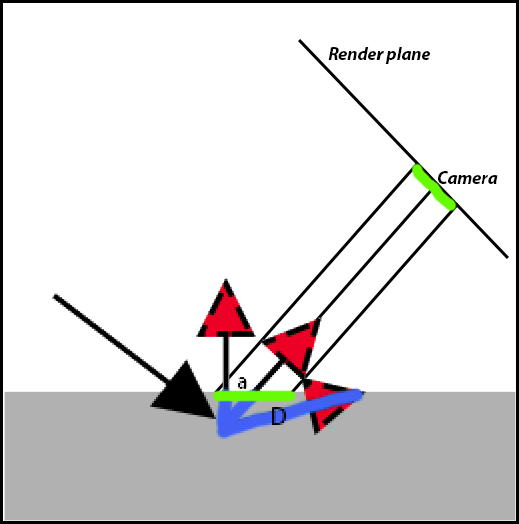 Now, look what will happen to the render result. A specific area on the render plane (say: a pixel), marked green in the illustration, gets its light from an area on the object surface (marked green as well). At skewer angles a between surface normal and camera, this area on the object gets larger: A = A0 / cos(a).
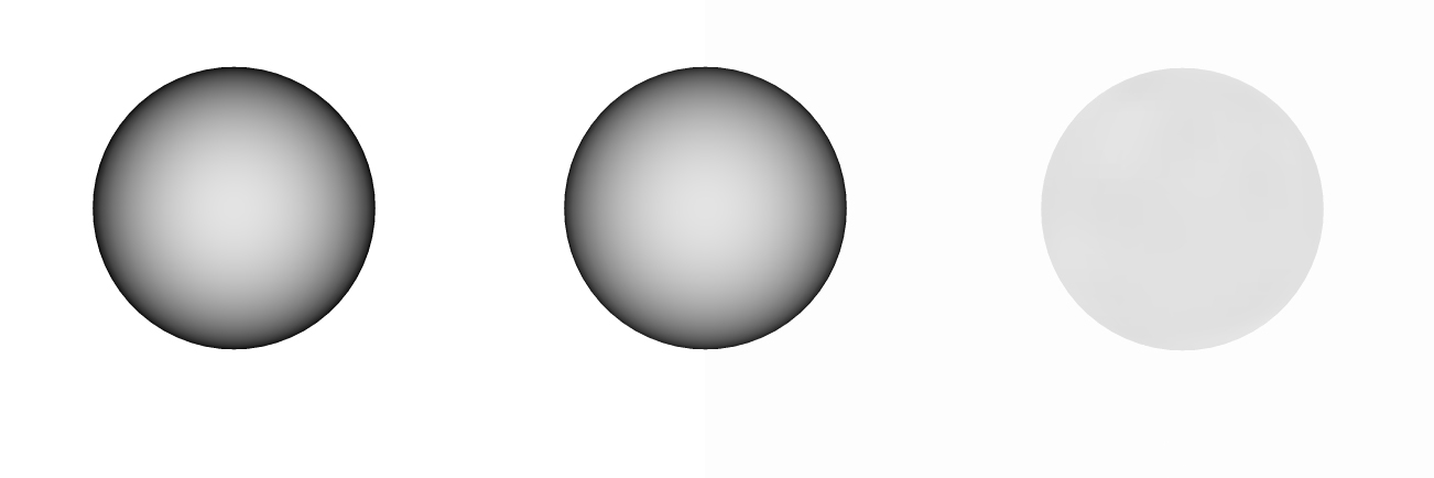

 This holds for Ambient and Translucence, and for Reflection and Refraction. Diffuse and Specular are similar, but include a build-in shader as well which manages the distribution of light intensities over the surface. See the