Nodes are the essential building blocks in the Advanced interface to the Poser Material Room. They are the graphical representation of mathematical function calls, that is: calculation procedures which turn parameters (inputs) to a result (output).
Intermediate
The default Diffuse property of materials offers a reasonable representation for smooth, hard materials. But for materials of a more porous nature the Clay node is a far better alternative. Think of skin, cloth, wood and all other kinds of natural stuff, brick, stone, non-glazed pottery, rubberish soft plastics, etcetera. Note though that some materials, especially skin and soft plastics or rubbers, have got some advanced alternatives in recent Poser versions. These are the various ‘scatter’ nodes. As can be expected, such alternatives do require more parameters, and more render time.
Anyway, like the Diffuse node the Clay node is meant to be plugged into the Alternate Diffuse slot (Advanced interface only), while having the Diffuse portion of the PoserSurface definition be zeroed out:
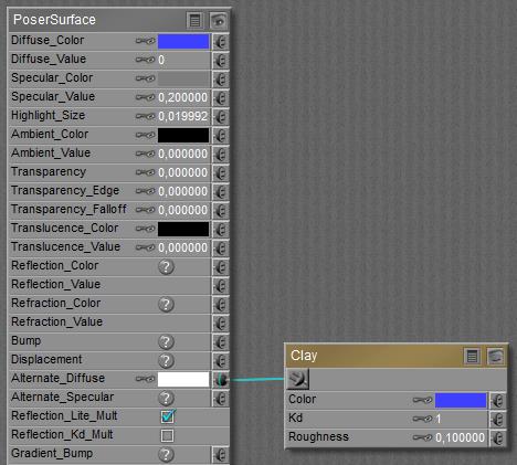
The Clay node offers Color and Kd for parameters which have the same meaning as Color and Value for Diffuse. The new kid on the block is: Roughness.
A low value makes the surface smooth, and the default 0.1 turns the Clay into a Diffuse equivalent. Lower values make no significant difference, but higher values (up to 1.0) do.

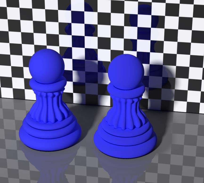
The scene above compares regular Diffuse (left) with Clay response (right) having Roughness set to 0.1. Specularity is at default value. I hardly see a difference: Diffuse is a special case of Clay.

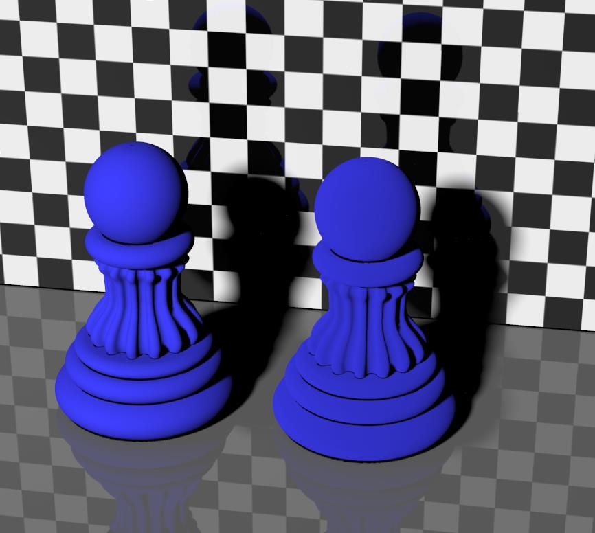
Both two scenes above have specularity turned OFF for demonstration purposes, and use the Clay node for diffuse response. Roughness is set to 0.1 (both left pawns, representing regular Diffuse) versus 0.5 (left image, right pawn) and versus 1.0 (right image, right pawn) respectively.
Maybe you’ve already noticed that the porous material, using the Clay node, re-emits less light in the forward direction (it’s slightly darker *) but experiences a reduced falloff near the edges (the higher the roughness, the less darkening at the sides reveal the shape of the object). The first is the result of the pores absorbing more light, the second is because the pores make the surface more irregular. The higher the Roughness, the more obvious this effect.
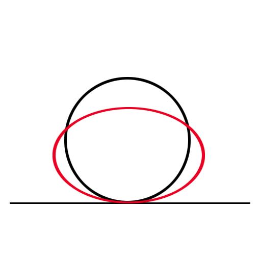 The graph shows this in another way. The black circle represents the light intensity from classic Lambert diffusion. Lots of light perpendicular from the surface, no light parallel to it, and a cosine fall-off for angles in between. The red curve represents the Clay effect: less light perpendicular compared to diffuse, but less intensity-falloff at the edges.
Surfaces with small pores (soft plastics, skin, plant leaves) will benefit from low roughness values, say 0.2 to 0.4 while surfaces with noticeable pores (brick, pottery) will benefit from larger values (0.7 to 0.9).
(*) since IDL light scenes will have the light coming from about all directions, the effect on light distribution – as being darker in the forward direction – will be less noticeable. Rendering with direct light only makes this Clay effect far stronger.
In the image above (with no specularity), the left pawn represents regular diffusion or clay with Roughness set to 0.1 while the right pawn represents clay with Roughness 1.0; just like the image before. But now, IDL lighting is OFF. Now the difference between them is much larger. This implies that when I render my scene under IDL conditions, it might become questionable whether it pays off to implement the clay node instead of regular diffuse.